Project 1.1.6: TRAFFIC LIGHT
| Description | This is an interesting project where you program three LEDS to turn on and go off one after the other. |
|---|---|
| Use case | In our society, we do have traffic lights that help direct cars and prevent accidents. |
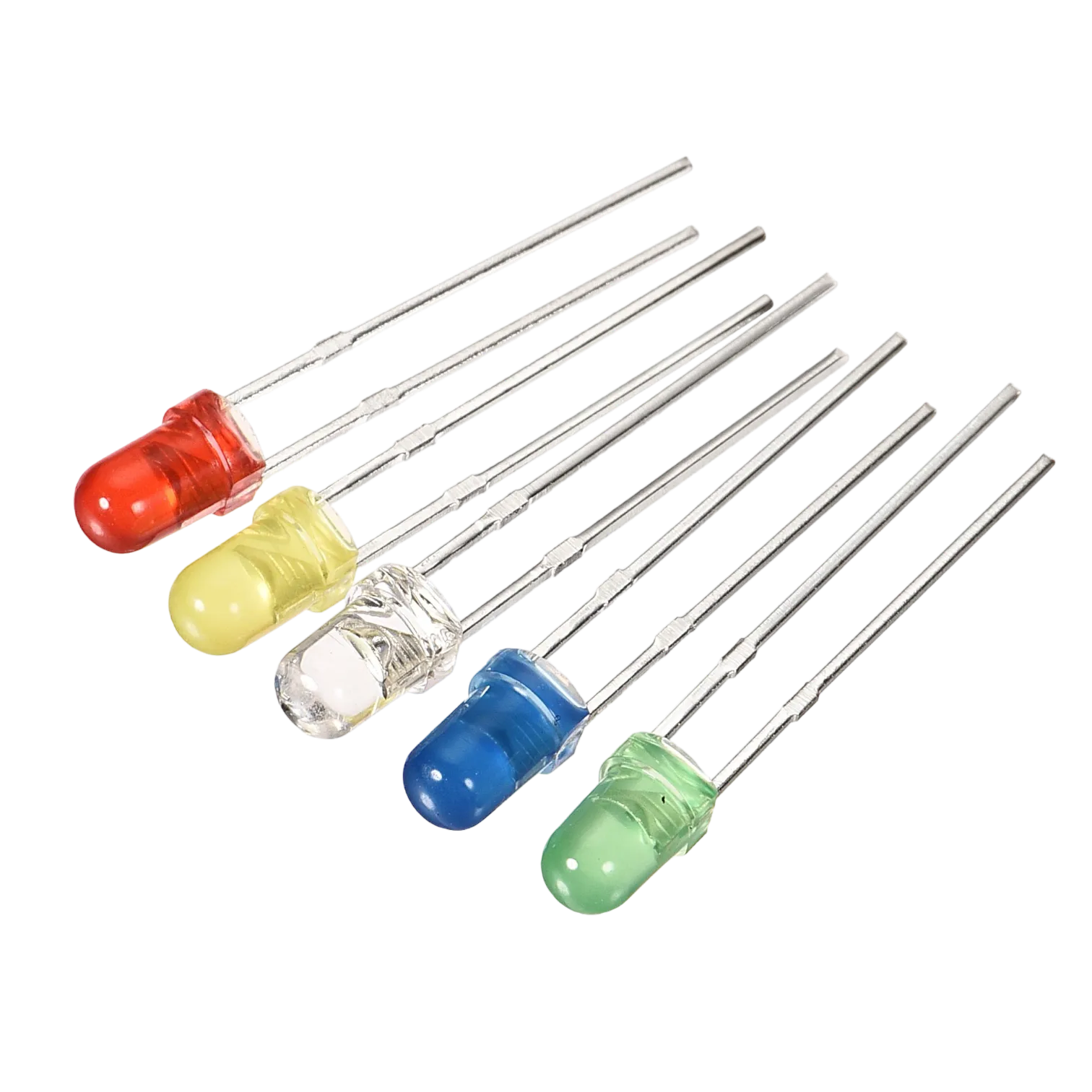
Components (Things You will need)
 |
 |
 |
 |
 |
|---|---|---|---|---|
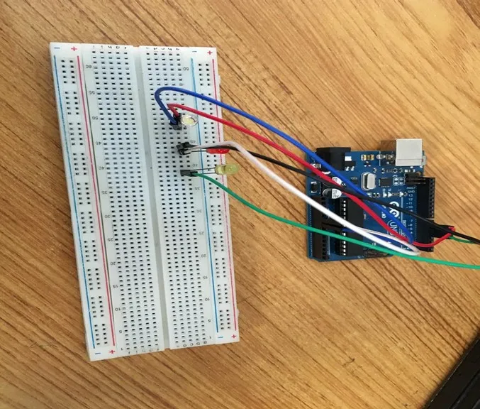
Building the circuit
Things Needed:
- Arduino Uno = 1
- Arduino USB cable = 1
- White LED = 1
- Red LED = 1
- Yellow LED = 1
- Red jumper wires = 1
- Blue jumper wires = 1
- Black jumper wires = 1
- White jumper wires = 1
- Green jumper wires = 1
- Purple jumper wires = 1
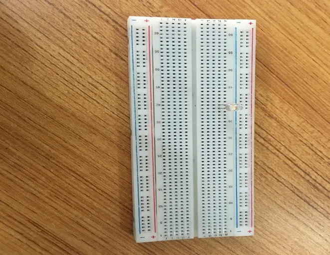
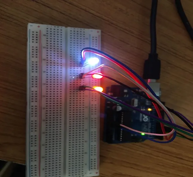
Mounting the component on the breadboard
Mounting the component on the breadboard
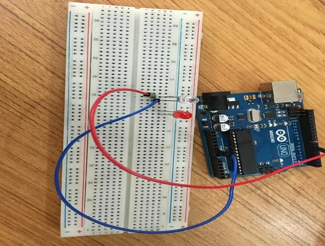
Step 1: Take the breadboard, the white LED and insert it into the vertical connectors on the breadboard.
 .
.
NB: Make sure you identify where the positive pin (+) and the negative pin (-) is connected to on the breadboard. The longer pin of the LED is the positive pin and the shorter one, the negative PIN.
WIRING THE CIRCUIT
Things Needed:
- Red male-male-to-male jumper wires = 1
- Black male-to-male jumper wires = 1
- White male-to-male jumper wires = 1
- Blue male-to-male jumper wires = 1
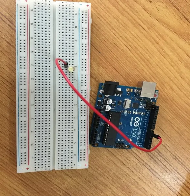
Step 2: Connect one end of red male-to-male jumper wire to the positive pin of the white LED on the breadboard and the other end to hole number 6 on the Arduino UNO.
 .
.
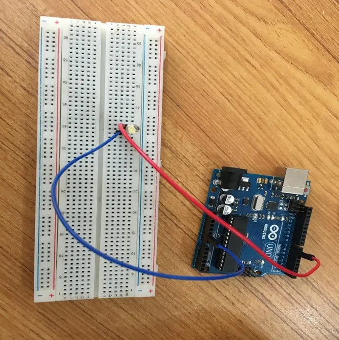
Step 3: Connect one end of the blue male-to-male jumper to the negative pin of the white LED on the breadboard and the other end to GND on the Arduino UNO.
 .
.
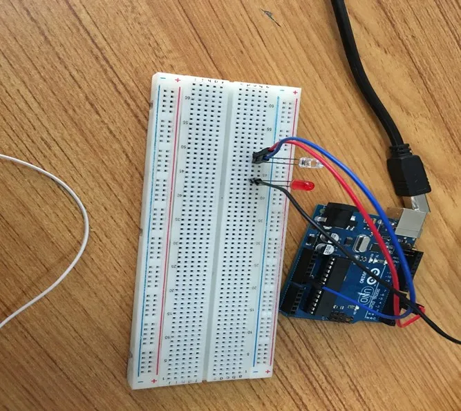
Step 4: Take the red LED and insert it into the vertical connectors on the breadboard.
 .
.
Step 5: Connect one end of the black male-to-male jumper wire to the positive pin of the red LED on the breadboard and the other end to hole number 5 on the Arduino UNO.
Step 6: Connect one end of the black male-to-male jumper wire to the positive pin of the red LED on the breadboard and the other end to hole number 5 on the Arduino UNO.
 .
.
Step 7: Connect one end of the white male-to-male jumper wire to the negative pin of the white LED on the breadboard and the other end to GND on the Arduino UNO.
 .
.
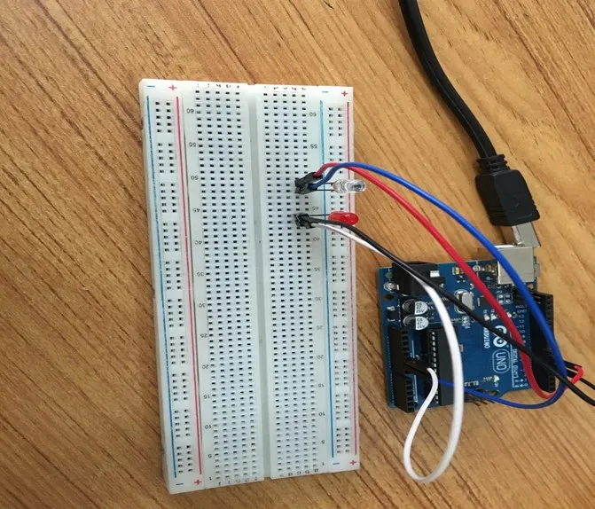
Step 8: Take the yellow LED and insert it into the vertical connectors on the breadboard.
 .
.
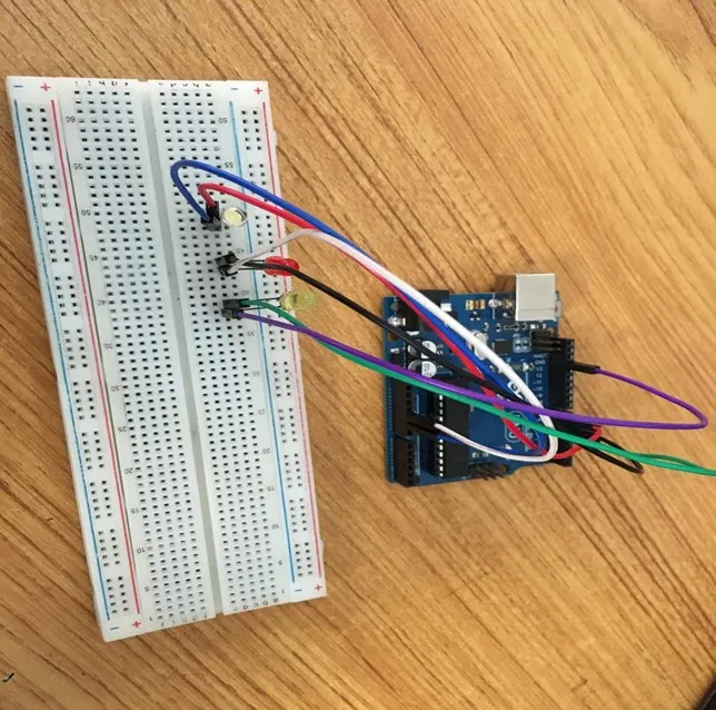
Step 9: Connect one end of the green male-to-male jumper wire to the positive pin of the yellow LED on the breadboard and the other end to hole number 4 on the Arduino UNO.
 .
.
Step 10: Connect one end of the purple male-to-male jumper wire to the negative pin of the yellow LED on the breadboard and the other end to GND on the Arduino UNO.
 .
.
make sure you connect the arduino usb use blue cable to the Arduino board.
PROGRAMMING
Step 1: Open your Arduino IDE. See how to set up here: Getting Started.
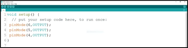
Step 2: Type the following codes in the void setup function as shown in the image below.
 .
.
NB: pinMode will help the Arduino board to decide which port should be activated. The code below will turn off the three light bulbs.
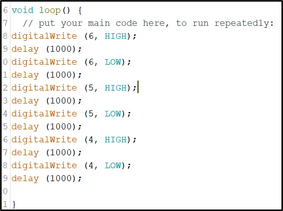
Step 3: Type the following codes in the void loop function.as shown in the image below;
digitalWrite (6, HIGH);
delay (1000);
digitalWrite (6, LOW);
delay (1000);
// this codes above will turn on and of the white LED

digitalWrite (5, HIGH);
delay (1000);
digitalWrite (5, LOW);
delay (1000);
// this codes above will turn on and of the red LED

digitalWrite (4, HIGH);
delay (1000);
digitalWrite (4, LOW);
delay (1000);
// this codes above will turn on and of the yellow LED
 .
.
_NB: To turn this LEDS off, you can change the “HIGH” in the ode into “LOW” _
Step 4: Save your code. See the Getting Started section
Step 5: Select the arduino board and port See the Getting Started section:Selecting Arduino Board Type and Uploading your code.
Step 6: Upload your code. See the Getting Started section:Selecting Arduino Board Type and Uploading your code
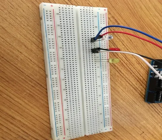
OBSERVATION
 .
.
CONCLUSION
In brief, the three-LED blinking project offers a hands-on introduction to coordinated LED control. By creating a blinking pattern across three LEDs, participants gain insights into circuit connections, programming loops, and synchronization. This endeavor serves as a stepping stone for more complex electronics undertakings while illustrating the concept of repetitive actions, sparking interest in practical electronics applications.