Project 2.5.1:LED Control with Arduino and Push Button
| Description | You will learn how to create a simple circuit using an Arduino micro-controller and a push button to turn on and Off |
|---|---|
| Use case | Imagine you want to create an interactive lighting system for your living room using Arduino and push buttons. You want to control the ambiance by turning on specific lights with a simple press of a button. |
Components (Things You will need)
 |
 |
 |
 |
 |
 |
|---|---|---|---|---|---|
Building the circuit
Things Needed:
- Arduino Uno = 1
- Arduino USB cable = 1
- Resistor = 1
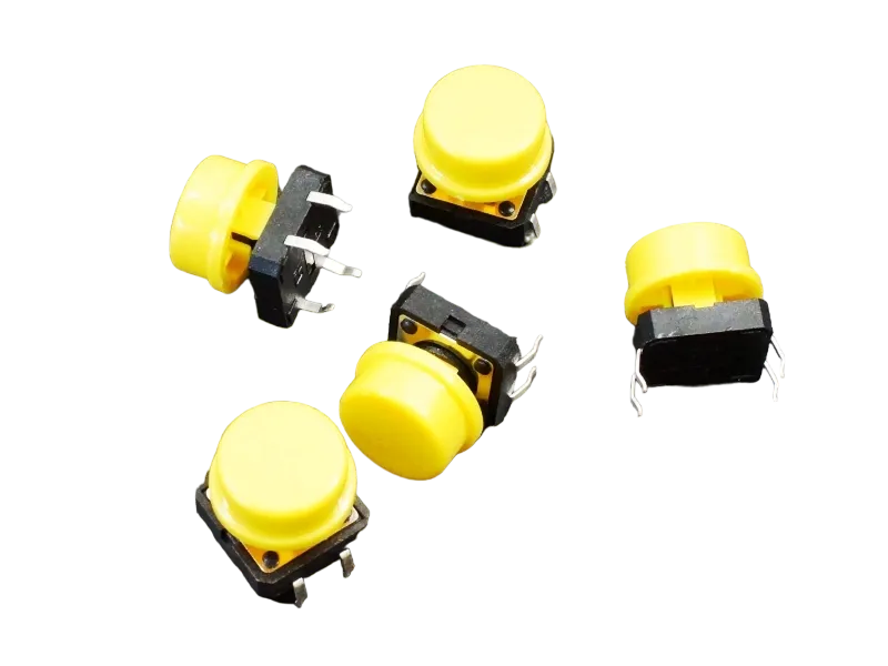
- Push button = 1
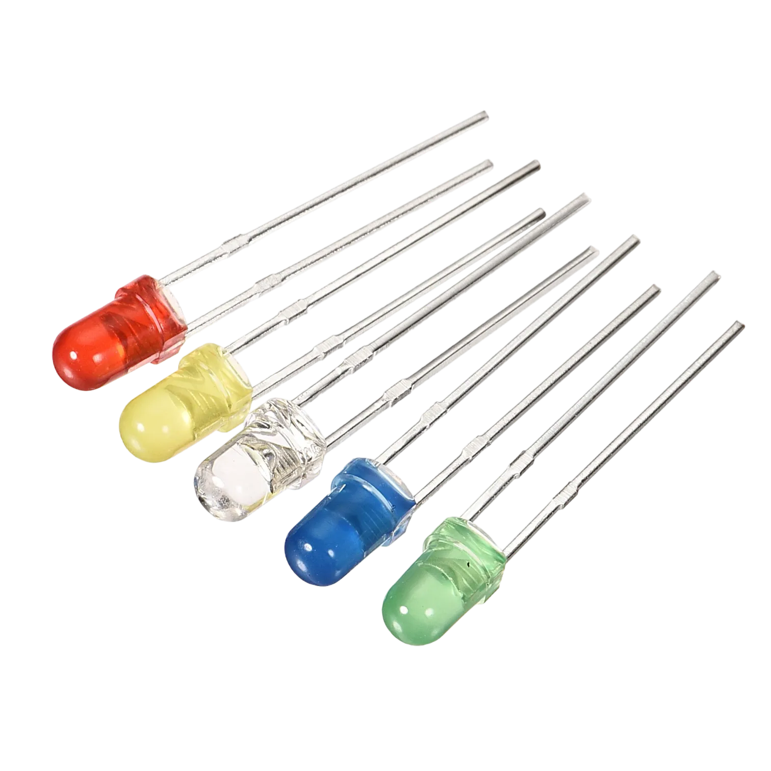
- Red LED = 1
- Blue jumper wire= 1
- Yellow jumper wire= 1
- Black jumper wire= 1
- Red jumper wire= 1
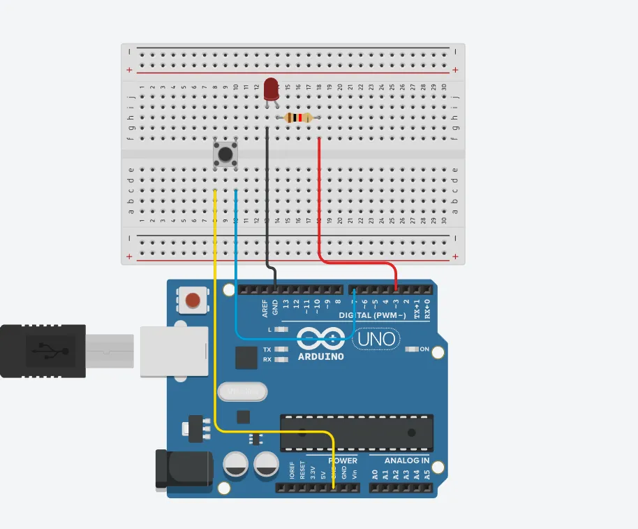
Mounting the component on the breadboard
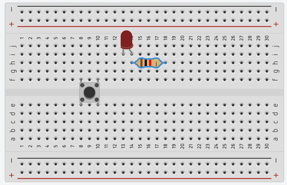
Step 1: Take the breadboard and the red LED and insert the red LED into the vertical connectors on the breadboard.
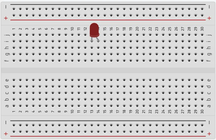 .
.
step 2: Connect the pushbutton on the breadboard but make sure the two pair of the pins are connected on each side of the bridge.
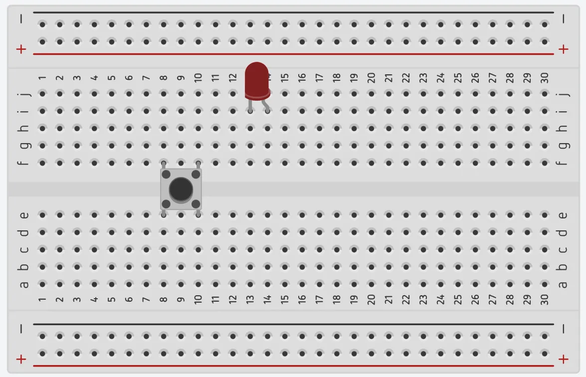 .
.
step 3: Take one resistor and connect one terminal of the resistor to the longer pin of the LED positive terminal (+) on the breadboard and the other pin of the resistor into the vertical connected wholes on the breadboard.
 .
.
Note: NB: This completes the circuit for the LED, allowing current to flow from the digital pin, through the LED and back to ground.
WIRING THE CIRCUIT
Things Needed:
- Blue jumper wire= 1
- Yellow jumper wire= 1
- Black jumper wire= 1
- Red jumper wire= 1
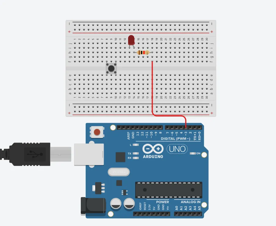
step 1: Connect red male-to-male jumper wire from the free end of the resistor to digital pin (13) on the Arduino UNO.
 .
.
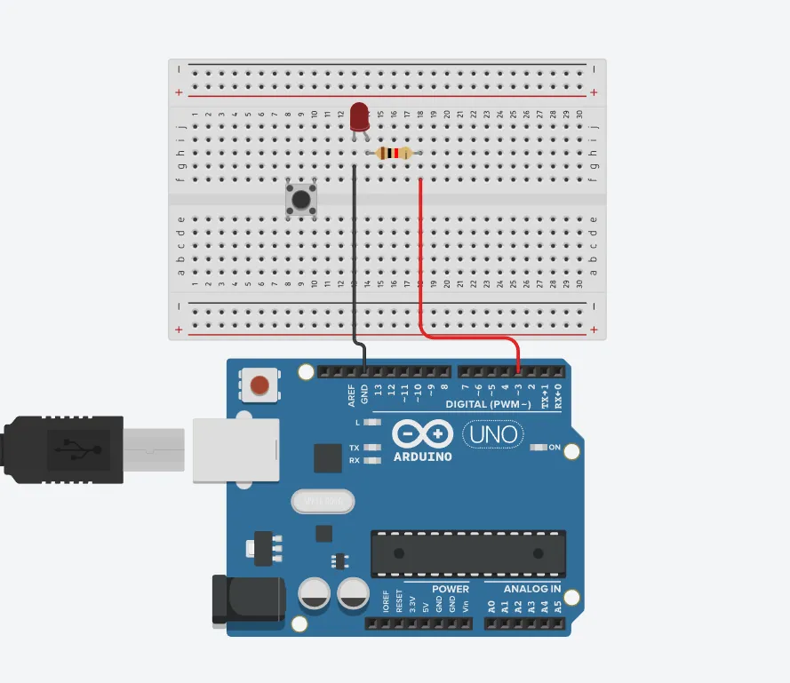
step 2: Connect Black male-to-male jumper wire from the free end of the LED negative pin power GND (Ground) on the Arduino UNO.
 .
.
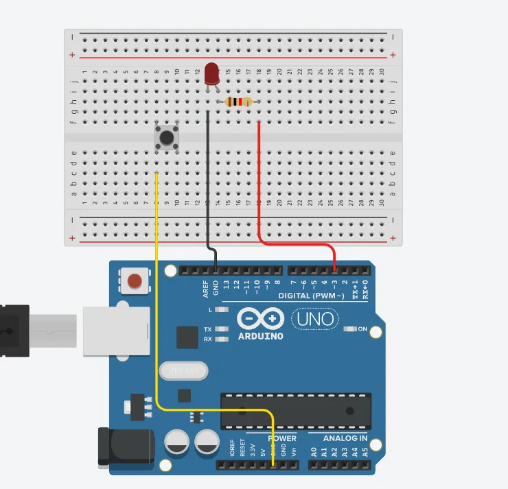
step 3: Connect Yellow male-to-male jumper wire from one Pin of the Push Button as a negative to power GND (Ground) on the Arduino UNO.
 .
.
step 4: Finally, connect blue male-to-male jumper wire from the other Pin of the push button (not connected to GND) to any digital pin on the Arduino UNO. Let's use digital pin 2 in this tutorial.
 .
.
PROGRAMMING
Step 1: Open your Arduino IDE. See how to set up here: Getting Started.
Step 2: Type the following codes before the void setup function.
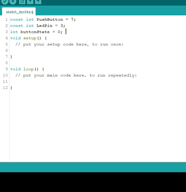 .
.
Step 3: After the void setup ()within the curly brackets type the following codes.
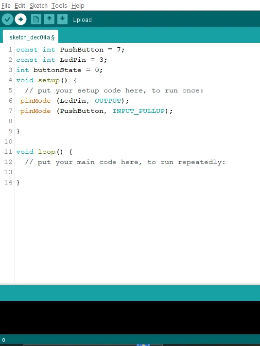 .
.
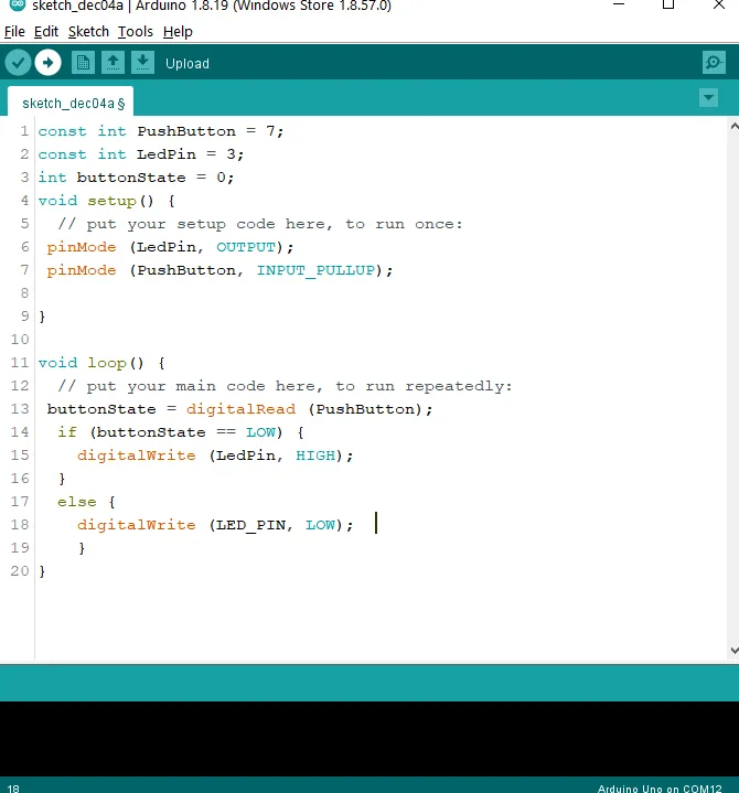
Step 4: : After the (void loop ()) within the curly brackets type
buttonState = digitalRead (PushButton);
  if (buttonState == LOW) {
    digitalWrite (LedPin, HIGH);
  }
  else {
    digitalWrite (LED_PIN, LOW);
    }
 .
.
Uploading the code
Step 1: Save your code. See the Getting Started section
Step 2: Select the arduino board and port See the Getting Started section:Selecting Arduino Board Type and Uploading your code.
Step 3: Upload your code. See the Getting Started section:Selecting Arduino Board Type and Uploading your code
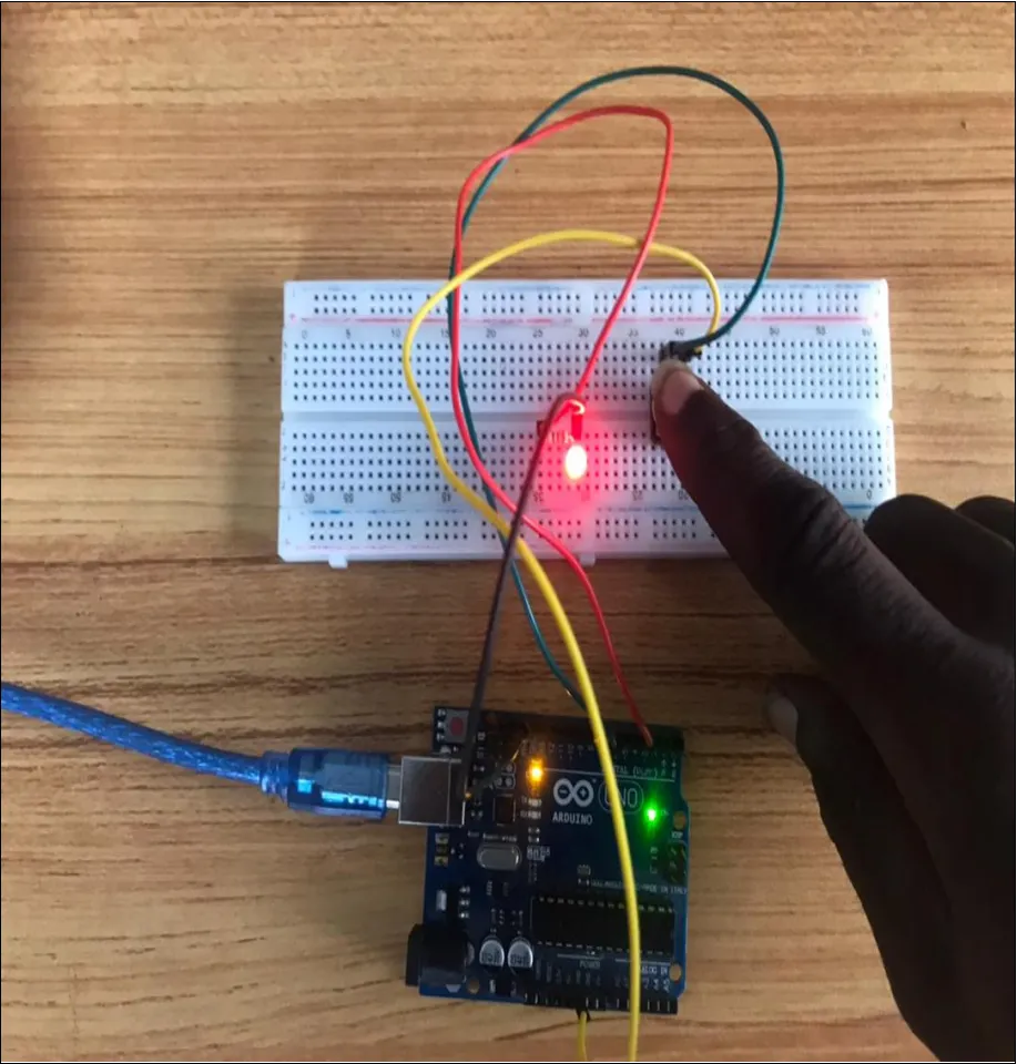
OBSERVATION
 .
.
 .
.
Push Button to turn off LED.
Step 1: Clear the previous code under void loop and type
CONCLUSION
The conclusion This Project is that, by connecting a push button and an LED to an Arduino board, you can create a circuit that allows you to turn on the LED when the push button is pressed. The circuit uses the digital input and output capabilities of the Arduino to detect the state of the push button and control the LED accordingly. By writing a simple Arduino code, the program continuously checks the state of the push button. When the button is pressed (reads LOW), the LED is toggled on or off by changing the state of the output pin connected to the LED. This allows the LED to turn on when the push button is pressed and turn off when it is released. This example serves as a basic introduction to using input and output devices with an Arduino board. It demonstrates the concept of digital input from the push button and digital output to control the LED. With this foundation, you can further explore and expand your knowledge in electronics and programming by incorporating additional sensors, actuators, or complex logic into your Arduino projects.