Project 2.8.1:STEMAIDE Pushbutton And RGB Control
| Description | You will learn how to create a simple circuit using a microcontroller, RGB module and a Pushbutton. |
|---|---|
| Use case | Imagine you want to use a sensor to on an LED of different color in your room after you press a pushbutton using Arduino. |
Components (Things You will need)
 |
 |
 |
 |
 |
 |
|---|---|---|---|---|---|
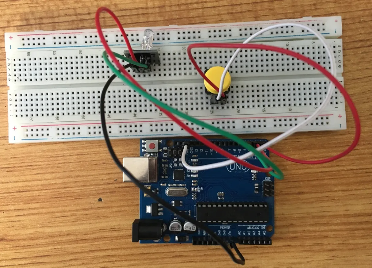
Building the circuit
Things Needed: - Arduino Uno = 1 - Arduino USB cable = 1 - RGB module= 1 - Breadboard = 1 - Pushbutton = 1 - Black male- male jumper wire = 1 - White male- male jumper wire = 1 - Red male- male jumper wire = 2 - Blue male- male jumper wire = 1 - Green male- male jumper wire = 1
Mounting the component on the breadboard
Things Needed:
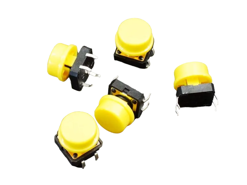
- Pushbutton = 1
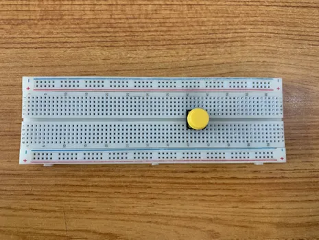
- Breadboard =1
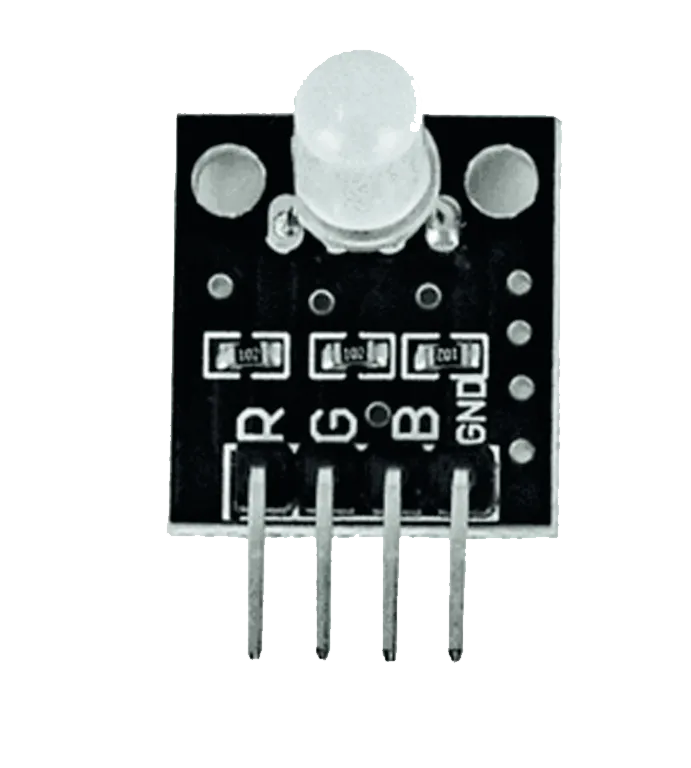
- RGB Module = 1
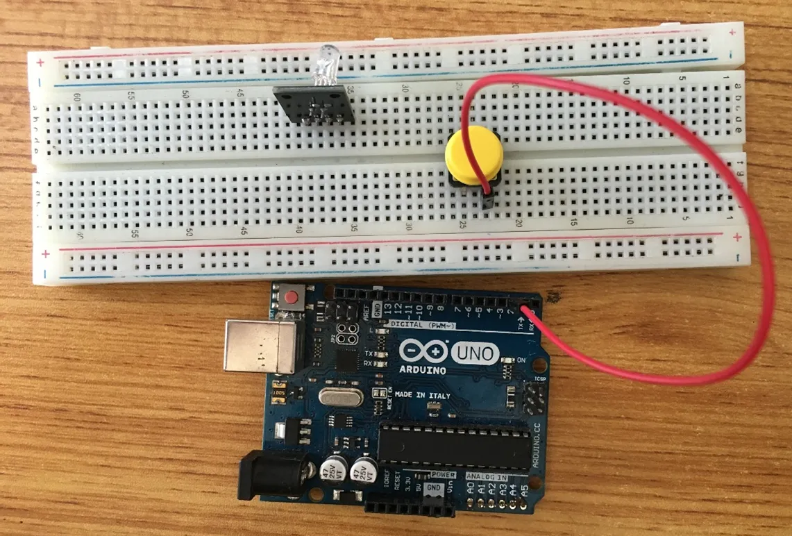
Step 1: - The push button has four unassigned pins. - On the middle section of the breadboard, locate each horizontal section lettered A to J. - Take the push button and insert two pins into the lettered section ‘g’ horizontally. - Insert the other two pins into the lettered section ‘d’ horizontally.
 .
.
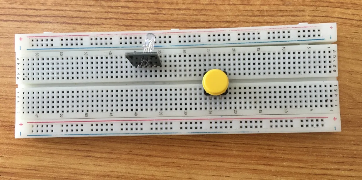
Step 2: - The RGB module has Four pins (Red, Green, Blue and Negative). These pins are labelled on the component - On the middle section of the breadboard, locate each horizontal section lettered A to J. - Take the RGB module and insert it into any of the lettered section (Say A) horizontally
 .
.
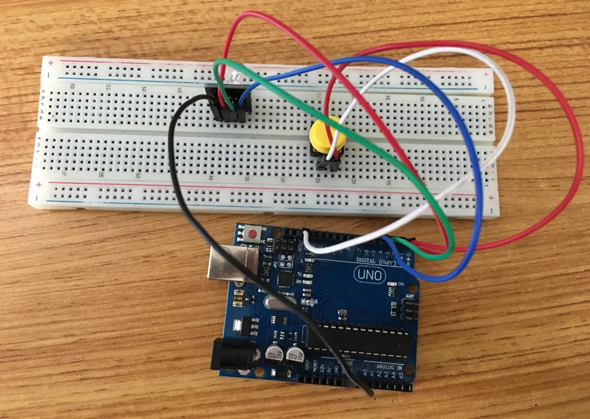
WIRING THE CIRCUIT
Things Needed:
- Black male- male jumper wire = 1
- White male- male jumper wire = 1
- Red male- male jumper wire = 2
- Blue male- male jumper wire = 1
- Green male- male jumper wire = 1
- Arduino Uno Board = 1
Step 3: Take the Red male-male-to-male jumper wire and place one side of the wire pin under the push button pin located on the lettered section ‘d’ and the other side of the wire pin to the digital pin 2 on the Arduino uno board. .
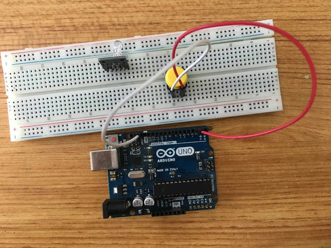
Step 4: Take the White male-male-to-male jumper wire and place one side of the wire pin under the other pin located on the lettered section ‘d’ and the other side of the wire pin to GND on the Arduino uno board.
 .
.
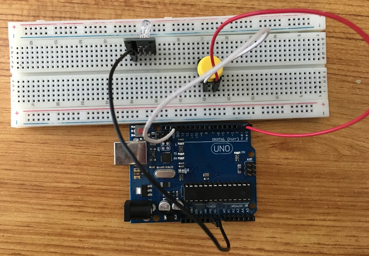
Step 5: Take the Black male-to-male jumper wire and place one side of the wire pin under the negative pin of the RGB module and the other side of the wire pin to GND on the Arduino Uno board.
 .
.
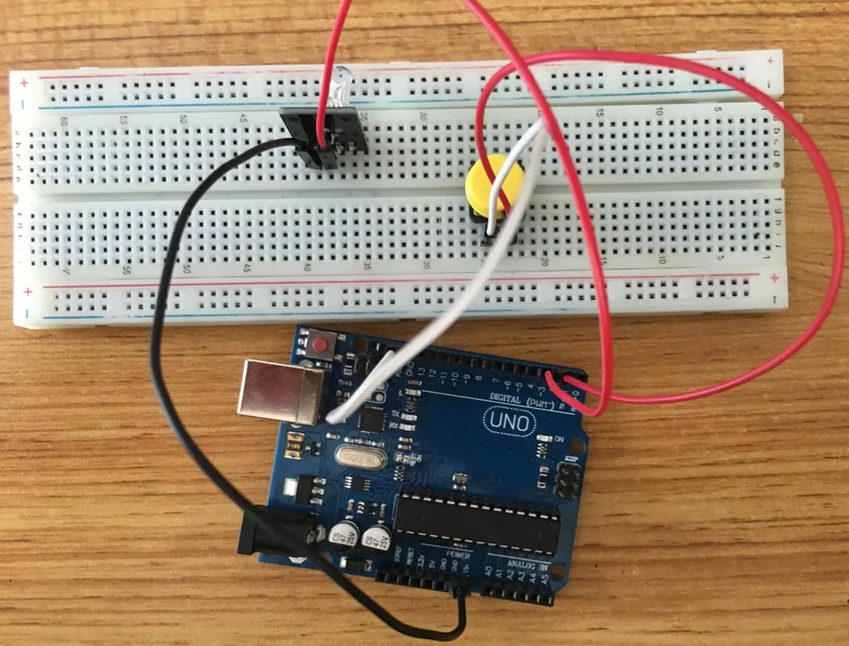
Step 6: Take the Red male-to-male jumper wire and place one side of the wire pin under the Red pin of the RGB module and the other side of the wire pin to digital pin 3 on the Arduino Uno board.
 .
.
Step 7: Take the Green male-to-male jumper wire and place one side of the wire pin under the Green pin of the RGB module and the other side of the wire pin to the digital pin 4 on the Arduino Uno board.
 .
.
Step 8: Take the Blue male-to-male jumper wire and place one side of the wire pin under the G pin of the RGB module and the other side of the wire pin to the digital pin 5 on the Arduino Uno board.
 .
.
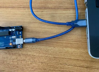
Connecting The Arduino Uno Board To Your Laptop.
Arduino Uno Board Arduino cable
Step 7: Connect the USB port of the Arduino cable to the USB port of your laptop and the other side to the Arduino Uno Board.
 .
.
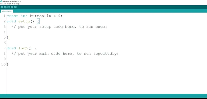
PROGRAMMING
Step 1: Open your Arduino IDE. See how to set up here: Getting Started.
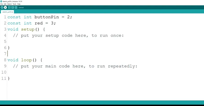
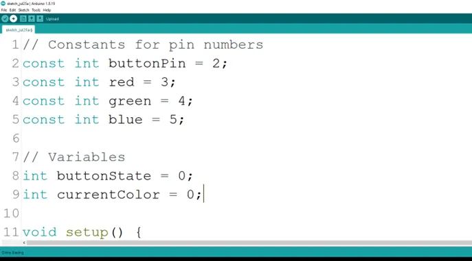
Step 2: Type const int buttonPin = 2; as shown in the picture below.
 .
.
Step 3: Type int red = 3; as shown in the picture below.
 .
.
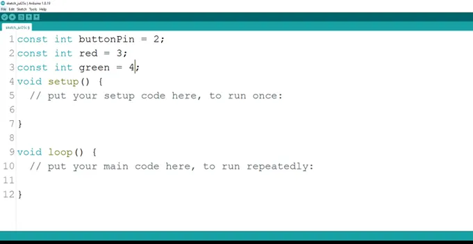
Step 4: Press ENTER to go to the next line, type int green = 4; to define the green pin as shown in the picture below.
 .
.
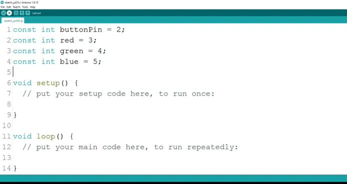
Step 5: Type int blue = 3;to define the pin for the blue pin as shown in the picture below.
 .
.
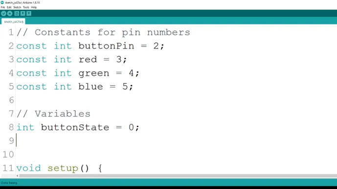
Step 6: Type int buttonState = 0; as shown in the picture below.
 .
.
Step 7: Type int currentColor = 0;to declare the current color state as shown in the picture below.
 .
.
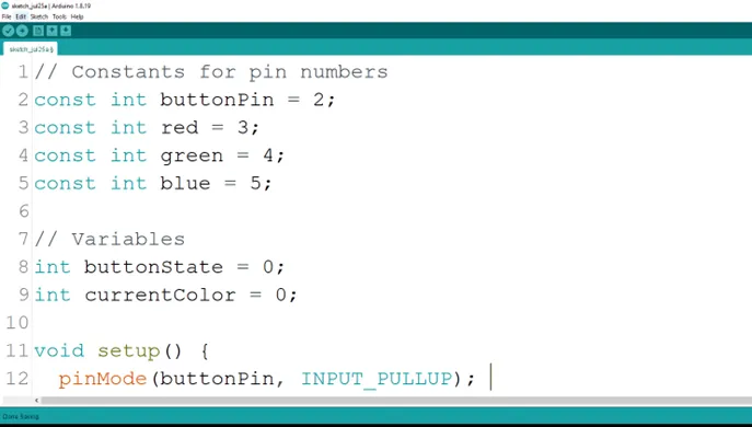
Step 8: Type Inside the curly brackets of the void setup () function, type pinMode (buttonPin, INPUT_PULLUP); to set the button pin as an input.
 .
.
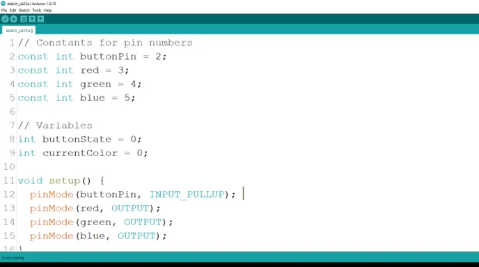
Step 9: After the (void setup ()) within the curly brackets type
pinMode (red, OUTPUT);
pinMode (green, OUTPUT);
pinMode (blue, OUTPUT); to set the RGB pins as an output.
 .
.
Step 10: Inside the curly brackets of the void loop (), which is where you put your code to run repeatedly. Type As shown in the picture below.
As shown in the picture below.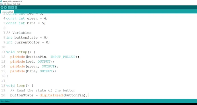 .
.
Step 11: Type
As shown in the picture below.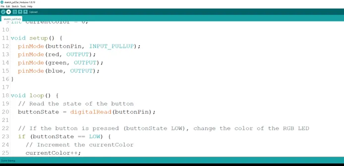 .
.
Step 12: Type
As shown in the picture below.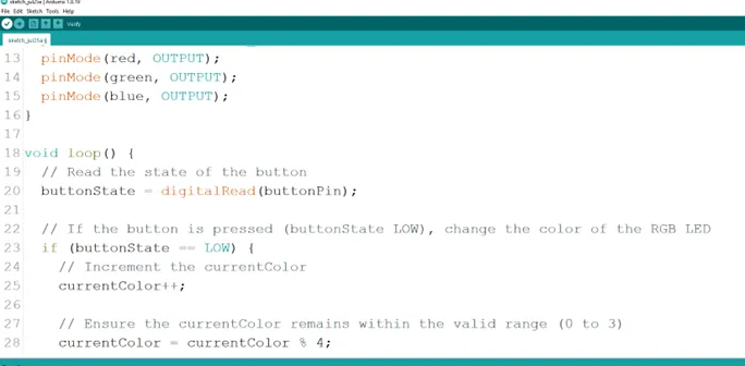 .
.
Step 13: Type
As shown in the picture below.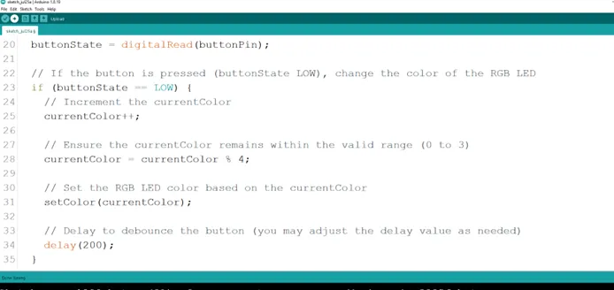 .
.
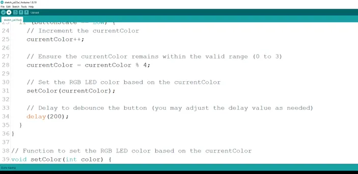
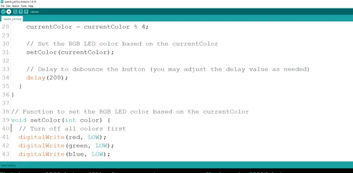
Step 14: Type a function ``` cpp void setColor (int color){
to set the RGB LED colors. As shown in the picture below.
.
**Step 15:** Type Function
``` cpp
digitalWrite (red, LOW);
digitalWrite (green, LOW);
digitalWrite (blue, LOW);
}
 .
.
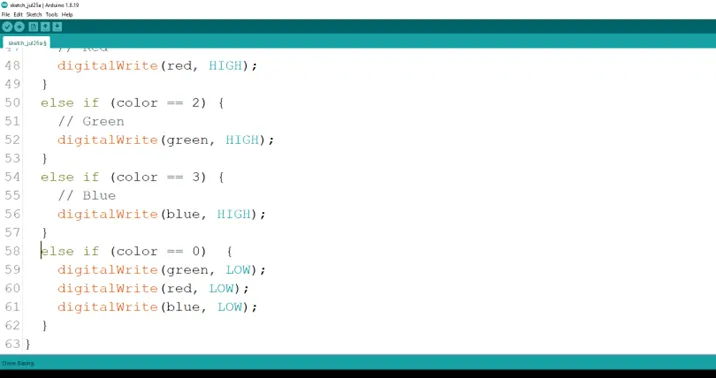
Step 16: Type the conditional statement to set the RGB color based on the current color.
As shown in the picture below.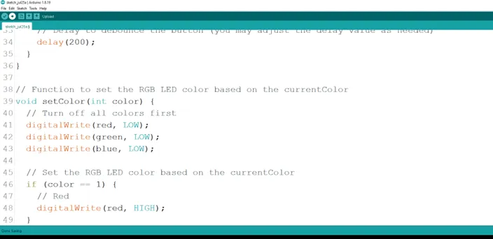 .
.
Step 17: Type the alternative for the conditional statement to set the RGB color based on the current color.
As shown in the picture below.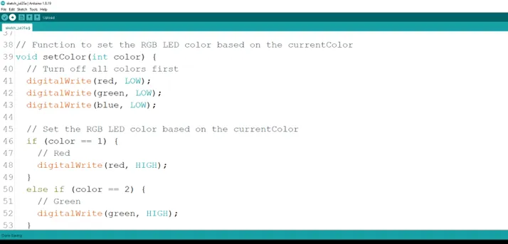 .
.
Step 18: Type the alternative for the conditional statement to set the RGB color based on the current color.
As shown in the picture below.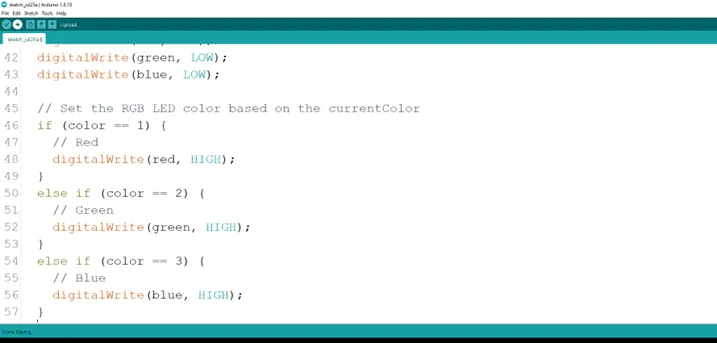 .
.
Step 19: Type the alternative for the conditional statement to set the RGB color based on the current color.
else if (color == 0) {
    digitalWrite (red, LOW);
     digitalWrite (green, LOW);
  digitalWrite (blue, LOW);
}
 .
.
Step 20: Save your code. See the Getting Started section
Step 21: Select the arduino board and port See the Getting Started section:Selecting Arduino Board Type and Uploading your code.
Step 22: Upload your code. See the Getting Started section:Selecting Arduino Board Type and Uploading your code
OBSERVATION
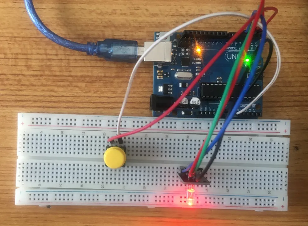
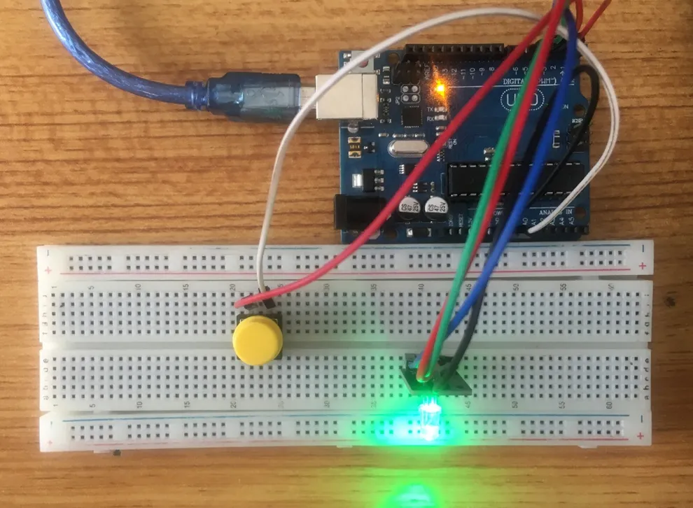
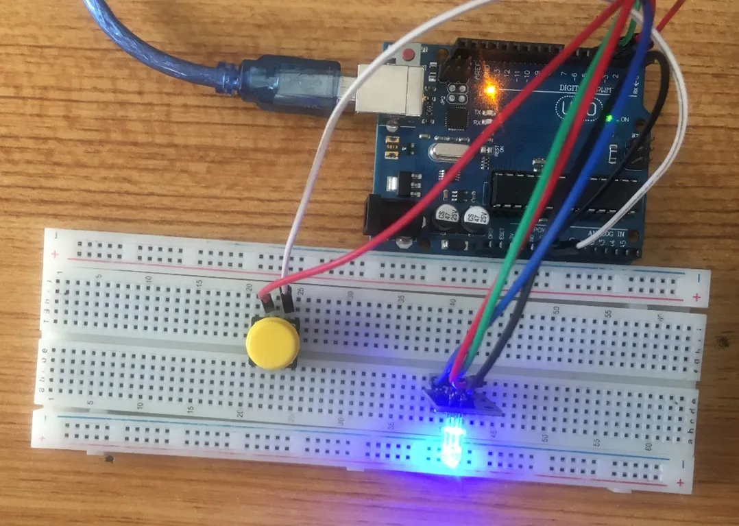
- Press the pushbutton several times to see the RGB display different LED colors.
 .
.
 .
.
 .
.
CONCLUSION
If you encounter any problems when trying to upload your code to the board, run through your code again to check for any errors or missing lines of code. If you did not encounter any problems and the program ran as expected, Congratulations on a job well done.