Project 3.6.2: Smart Trafic Light System.
| Description | This project demonstrates a smart pedestrian traffic light system using an ultrasonic sensor and a traffic light module. The ultrasonic sensor detects the presence of pedestrians near the crossing area, and the traffic lights respond automatically to allow safe crossing and improve pedestrian safety. |
|---|---|
| Use case | This project can be used at pedestrian crossings where the ultrasonic sensor detects people waiting to cross the road and automatically changes the traffic lights to allow safe pedestrian movement. |
Components (Things You will need)
 |
 |
 |
 |
 |
 |
|---|---|---|---|---|---|
Building the circuit
Things Needed:
- Arduino Uno Board = 1
- Arduino USB cable = 1
- Breadboard = 1
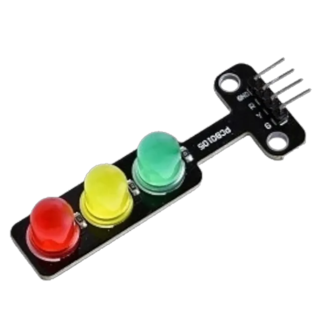
- Traffic Light 1
- Jumper Wires
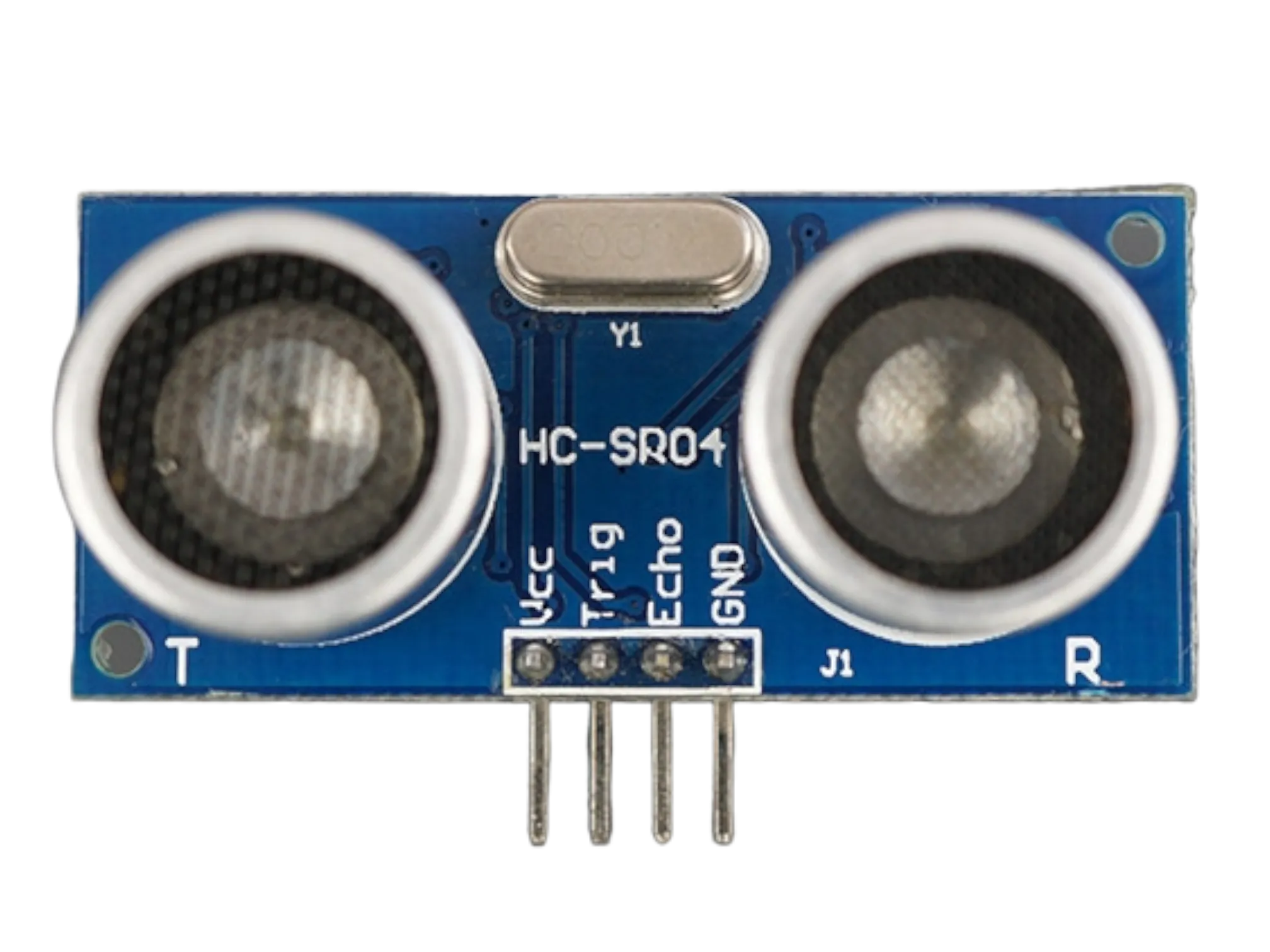
- Ultrasonic sensor = 1
Mounting the component on the breadboard
Things needed:
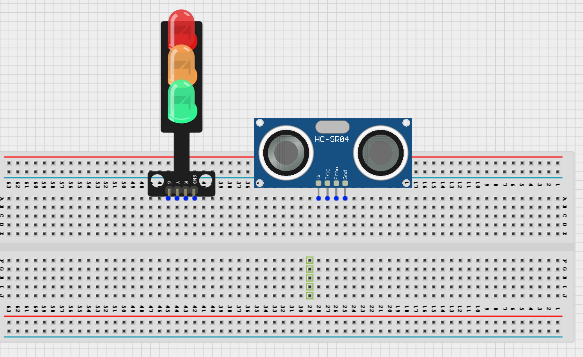
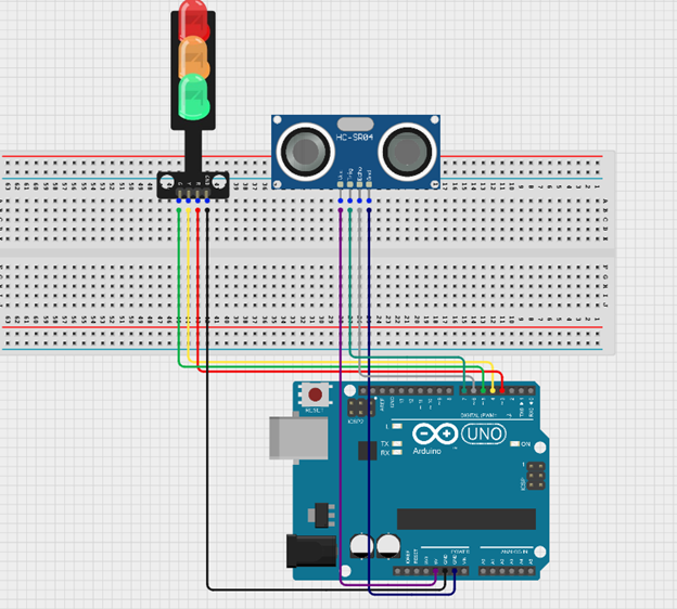
Step 1: Insert the ultrasonic sensor into the breadboard. Then place the traffic light module beside it, ensuring all the pins are properly inserted and firmly connected.
 .
.
WIRING THE CIRCUIT
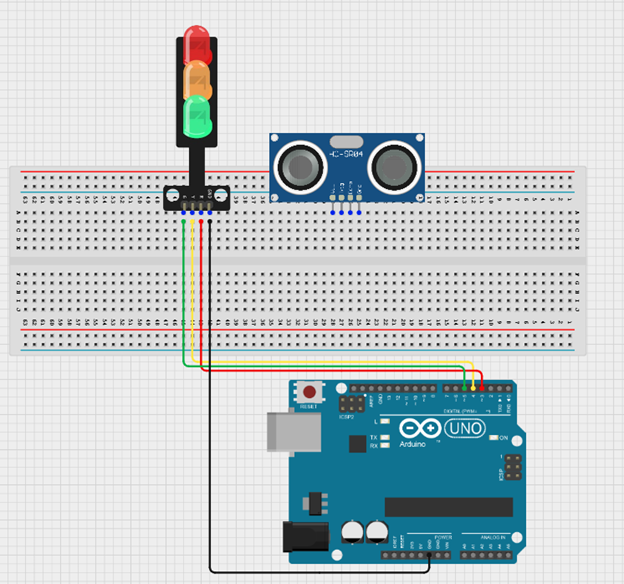
Step 2: Connect the GND pin of the traffic light module to the GND on the Arduino Uno using a jumper wire. Then connect the Red pin to Digital Pin 3, the Yellow pin to Digital Pin 4, and the Green pin to Digital Pin 5 on the Arduino Uno using jumper wires.
 .
.
Step 3: Connect the ultrasonic sensor to the Arduino Uno by linking the VCC pin to 5V, the GND pin to GND, the TRIG pin to Digital Pin 7, and the ECHO pin to Digital Pin 6 using jumper wires as shown in the circuit setup.
 .
.
PROGRAMMING
Step 1: Open your Arduino IDE. See how to set up here: Getting Started.
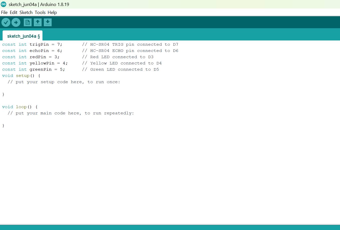
Step 2: Before the void setup() function, type:
const int trigPin = 7;       // HC-SR04 TRIG pin connected to D7
const int echoPin = 6;       // HC-SR04 ECHO pin connected to D6
const int redPin = 3;        // Red LED connected to D3
const int yellowPin = 4;     // Yellow LED connected to D4
const int greenPin = 5;      // Green LED connected to D5
 .
.
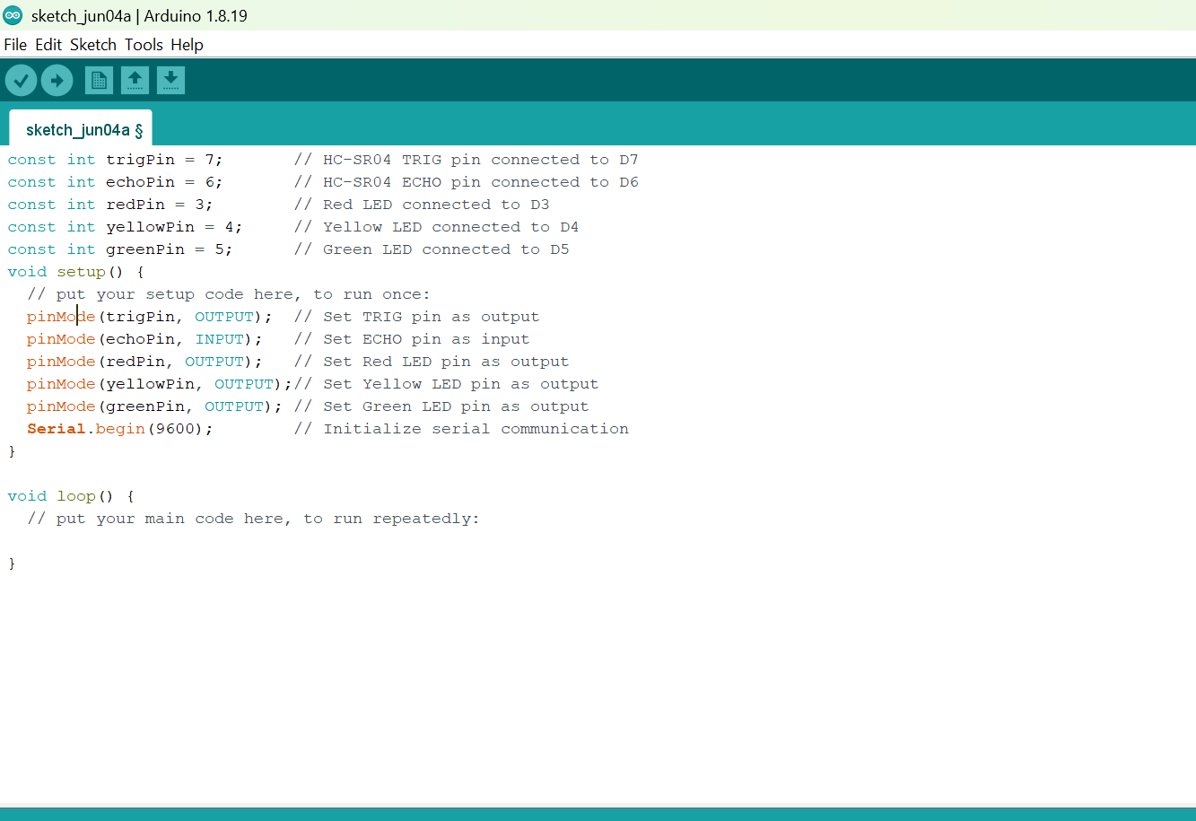
Step 3: Inside the void setup() function, type:
 pinMode(trigPin, OUTPUT);  // Set TRIG pin as output
  pinMode(echoPin, INPUT);   // Set ECHO pin as input
  pinMode(redPin, OUTPUT);   // Set Red LED pin as output
  pinMode(yellowPin, OUTPUT);// Set Yellow LED pin as output
  pinMode(greenPin, OUTPUT); // Set Green LED pin as output
  Serial.begin(9600);        // Initialize serial communication
 .
.
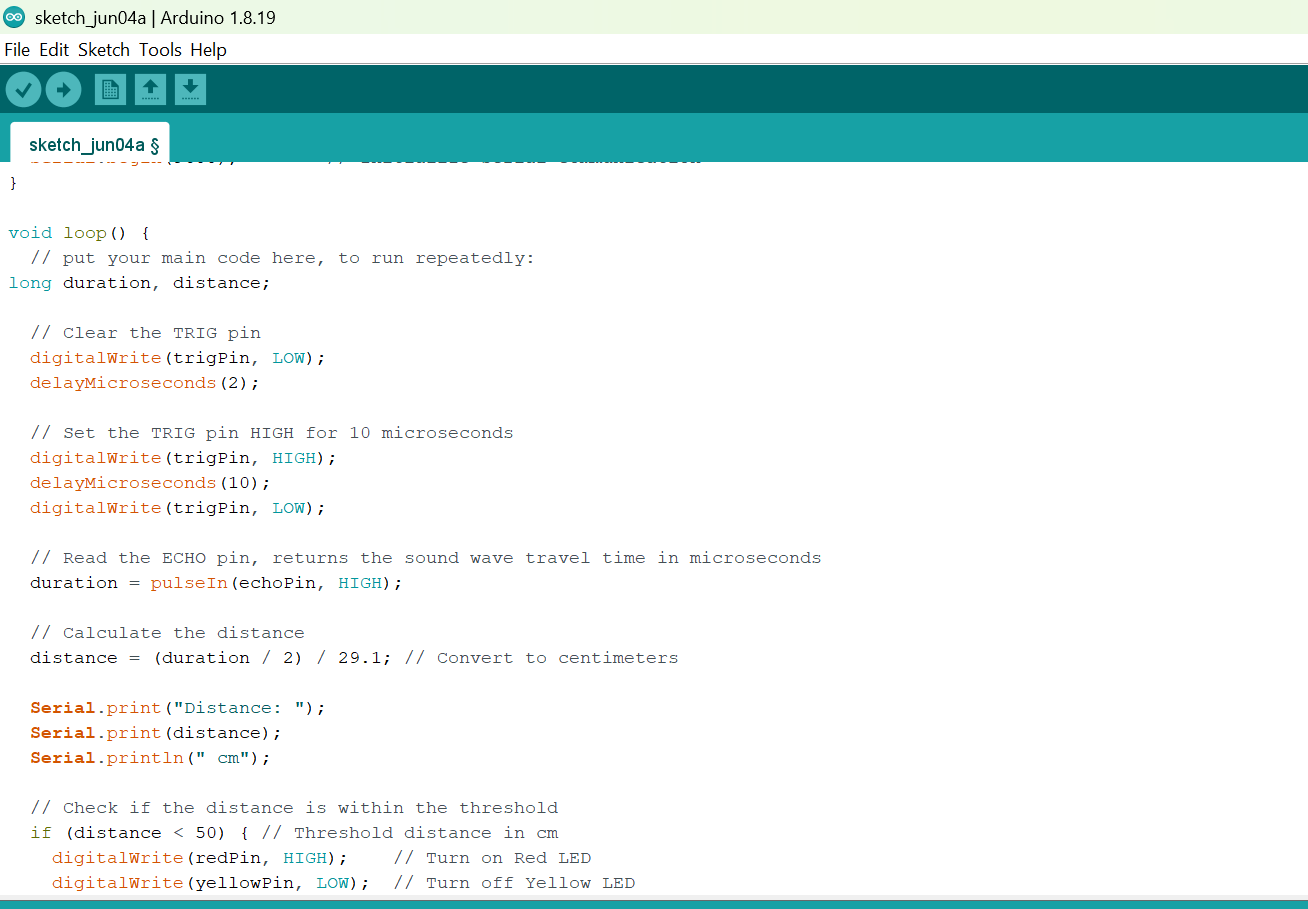
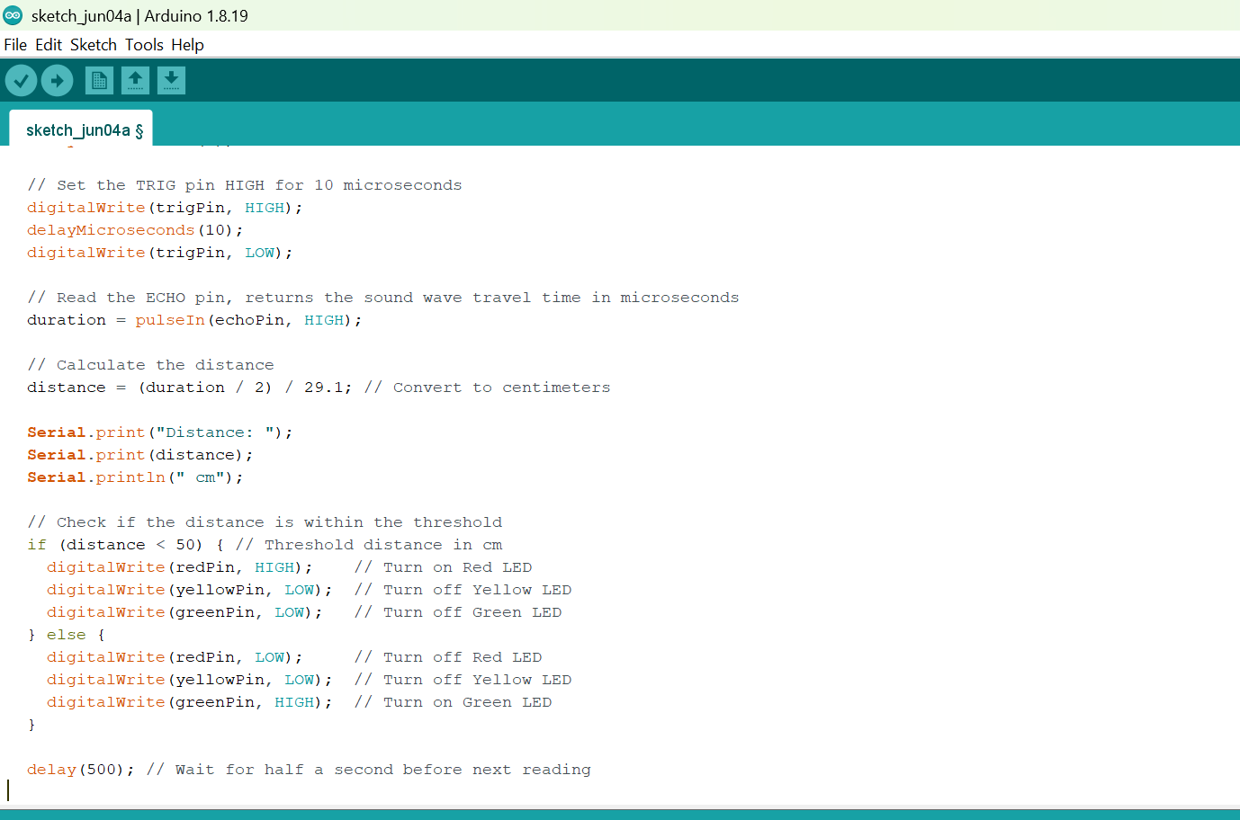
Step 4: Inside the void loop()function, type
 long duration, distance;

  // Clear the TRIG pin
  digitalWrite(trigPin, LOW);
  delayMicroseconds(2);

  // Set the TRIG pin HIGH for 10 microseconds
  digitalWrite(trigPin, HIGH);
  delayMicroseconds(10);
  digitalWrite(trigPin, LOW);

  // Read the ECHO pin, returns the sound wave travel time in microseconds
  duration = pulseIn(echoPin, HIGH);

  // Calculate the distance
  distance = (duration / 2) / 29.1; // Convert to centimeters

  Serial.print("Distance: ");
  Serial.print(distance);
  Serial.println(" cm");

  // Check if the distance is within the threshold
  if (distance < 50) { // Threshold distance in cm
    digitalWrite(redPin, HIGH);    // Turn on Red LED
    digitalWrite(yellowPin, LOW);  // Turn off Yellow LED
    digitalWrite(greenPin, LOW);   // Turn off Green LED
  } else {
    digitalWrite(redPin, LOW);     // Turn off Red LED
    digitalWrite(yellowPin, LOW);  // Turn off Yellow LED
    digitalWrite(greenPin, HIGH);  // Turn on Green LED
  }

  delay(500); // Wait for half a second before next reading
 .
.
 .
.
Step 19: Save your code. See the Getting Started section
Step 20: Select the arduino board and port See the Getting Started section:Selecting Arduino Board Type and Uploading your code.
Step 21: Upload your code. See the Getting Started section:Selecting Arduino Board Type and Uploading your code
CONCLUSION
This project demonstrated how an ultrasonic sensor can be used with a traffic light module and an Arduino Uno to create a smart pedestrian traffic light system. It helped in understanding object detection, automatic traffic control, and how sensors can improve pedestrian safety in real-life applications.