Project 1.5.4: GREEN BLINK
| Description | A blinking green LED means the system is working normally and everything is okay. |
|---|---|
| Use case | A blinking green LED can be used in real-life systems to indicate that a device is active and working properly, often showing normal operation or that a process is currently running, such as a system booting up, data processing, or a machine functioning without errors. |
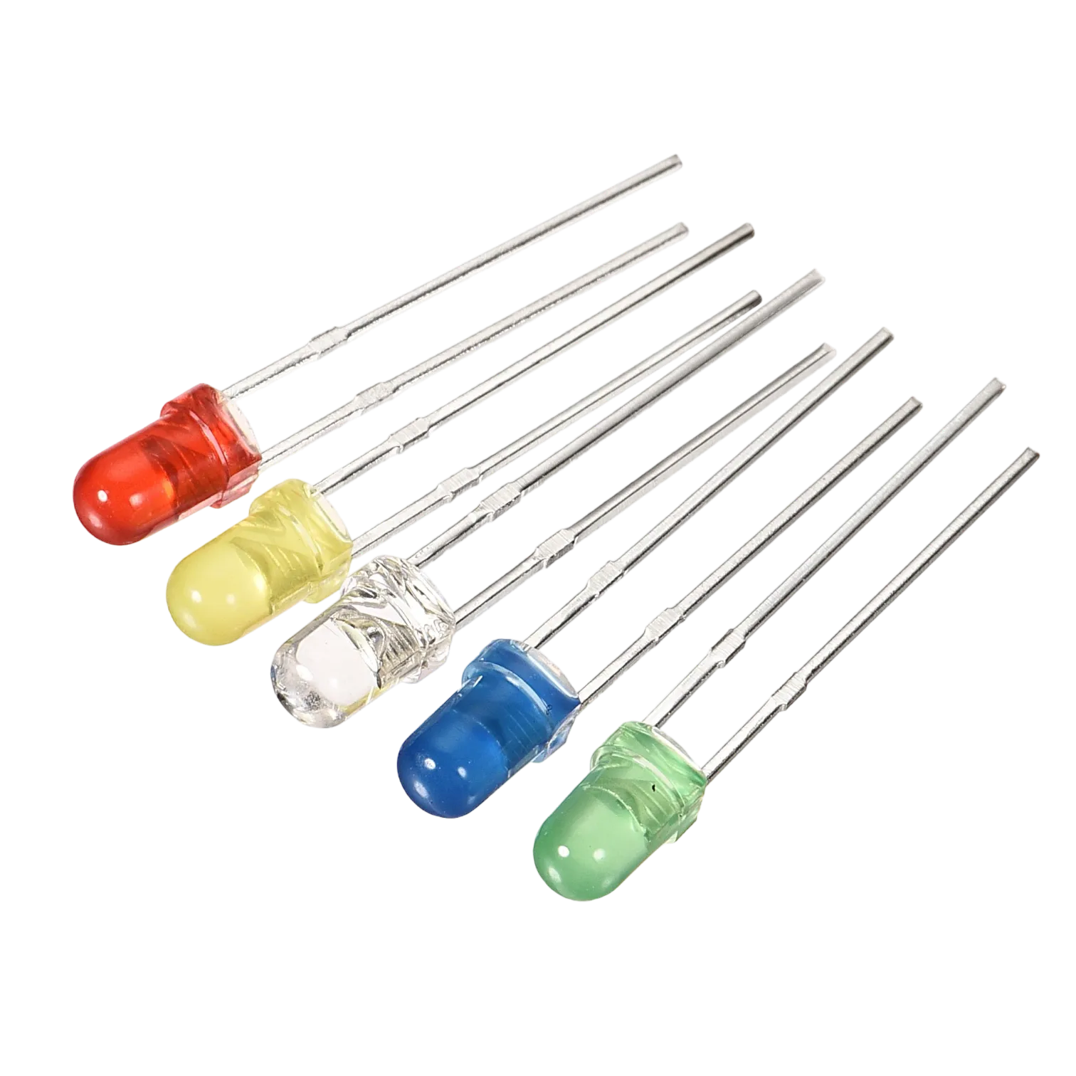
Components (Things You will need)
 |
 |
 |
 |
 |
 |
|---|---|---|---|---|---|
Building the circuit
Things Needed:
- Arduino Uno Board = 1
- Arduino USB cable = 1
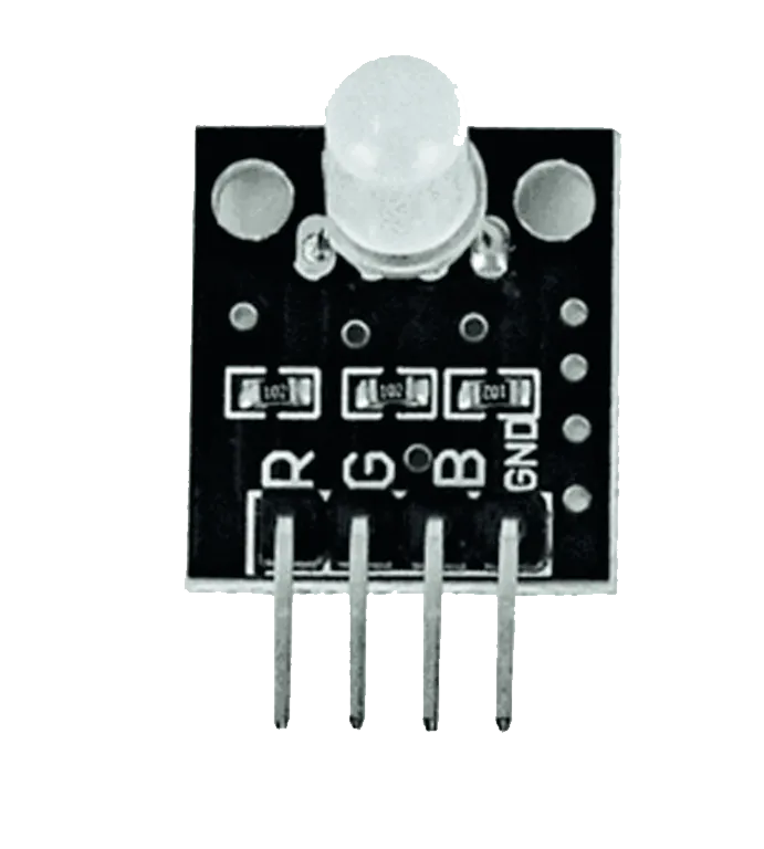
- RGB= 1
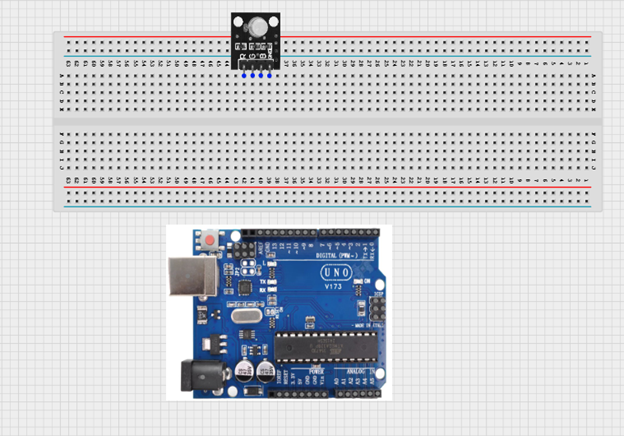
Mounting the component on the breadboard
Step 1: Insert the RGB module into the middle section of the breadboard horizontally. Make sure you identify the G pin (Green) and the – pin (GND).
NB: Take note of where each of the pins of the RGB are placed on the bread board.
 .
.
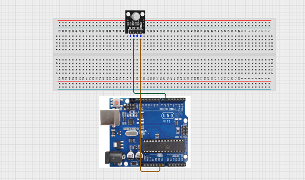
WIRING THE CIRCUIT
Things Needed:
- Brown jumper wire = 1
- Green jumper wire = 1
Step 2: Connect the green jumper wire from the G pin of the RGB module to pin 6 on the Arduino UNO. Then connect the brown jumper wire from the – (GND) pin of the RGB module to the GND pin on the Arduino UNO.
 .
.
PROGRAMMING
Step 1: Open your Arduino IDE. See how to set up here: Getting Started.
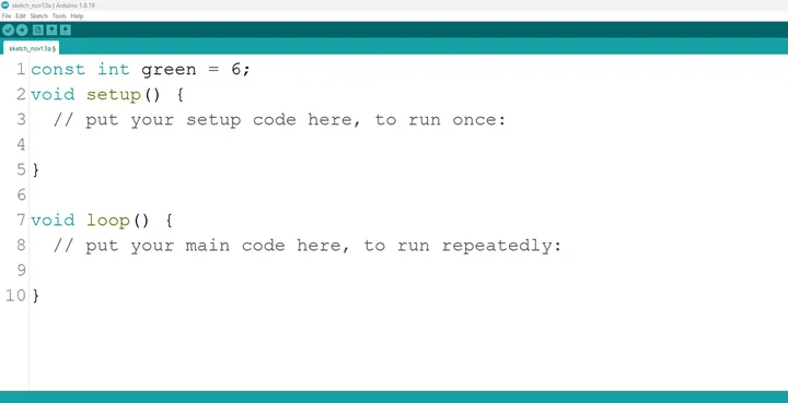
Step 2: Type as shown below in the image.
const int red = 6;
NB: Make sure you avoid errors when typing. Do not omit any character or symbol especially the bracket { } and semicolons ; and put them as you see in the image. The code that comes after the two ash backslashes “//” are called comments. They are not part of the code that will be run, they only explain the lines of code. You can avoid typing them.
 .
.
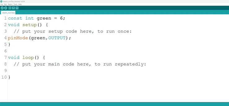
Step 3: Type as shown below in the image.
pinMode (green, OUTPUT);
 .
.
NB: The code below sets the pin names “green” as an output pin. An output pin helps send signals from the microcontroller to other components in the circuit. The pinMode () function, helps determine and control the behavior of a specific pin on the board
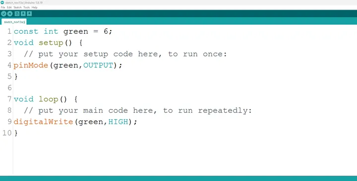
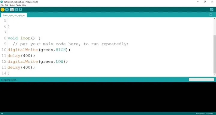
Step 4: Type as shown below in the image.
digitalWrite (green, HIGH);
 .
.
The digitalWrite () function controls the state of the pin. The pin can either be HIGH or LOW. The HIGH state turns on the LED. As a result, the code below turns on the LED.
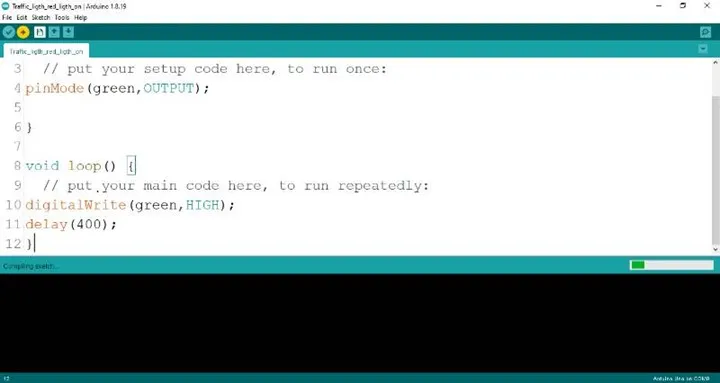
Step 5: Type as shown below
delay (400);
 .
.
Step 6: Type as seen below:
digitalWrite (green, LOW);
 .
.
Step 7: Type as shown below.
delay (400);
 .
.
Step 8: Save your code. See the Getting Started section
Step 9: Select the arduino board and port See the Getting Started section:Selecting Arduino Board Type and Uploading your code.
Step 10: Upload your code. See the Getting Started section:Selecting Arduino Board Type and Uploading your code
CONCLUSION
In brief, the project centered on creating a blinking green light within an RGB configuration offers a captivating insight into color manipulation and electronic control. By programming the green LED component to blink, participants gain understanding in timing control, code logic, and the dynamic visual effects of a single color. This endeavor marks an important milestone in exploring RGB color variation, showcasing the rhythmic potential of individual color components, and igniting curiosity in practical applications such as animated lighting displays and creative visual presentations.