Project 1.1.9: INCREASING BRIGHTNESS IN A ROOM
| Description | This project shows how to turn on five LEDs at the same time using an Arduino Uno. It introduces the control of several LEDs using different Arduino pins. |
|---|---|
| Use case | This project can represent a lighting system where many LEDs turn on together to increase brightness in a room. |
Components (Things You will need)
 |
 |
 |
 |
 |
 |
|---|---|---|---|---|---|
Building the circuit
Things Needed:
- Arduino Uno = 1
- Arduino USB cable = 1
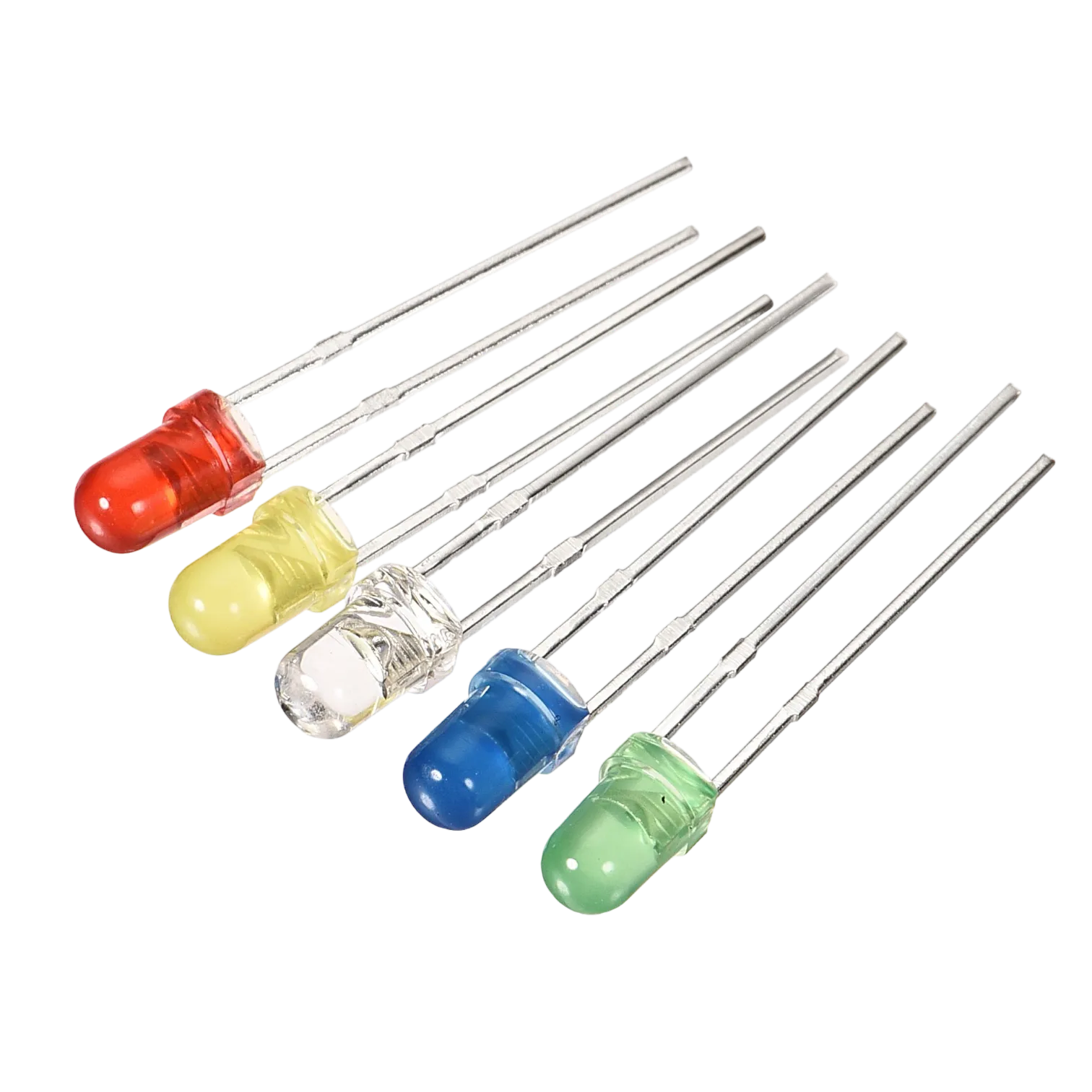
- LEDs = 5
- Jumper wire = 10
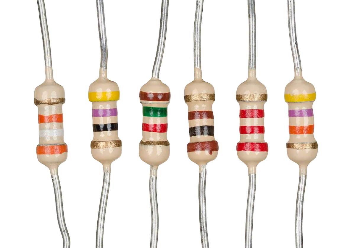
- Resistors = 5
Mounting the component on the breadboard
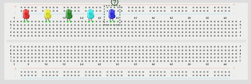
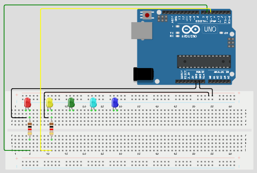
Step 1: Place the five LEDs on the breadboard. For each LED, the longer leg is the positive pin, while the shorter leg is the negative pin.
 .
.
NB: Make sure you identify where the positive pin (+) and the negative pin (-) is connected to on the breadboard. The longer pin of the LED is the positive pin and the shorter one, the negative PIN.
WIRING THE CIRCUIT
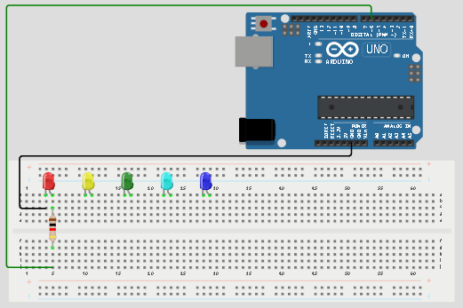
Step 2: Connect the positive leg of the first LED to pin 6 on the Arduino through a 220Ω resistor. Connect its negative leg to GND.
 .
.
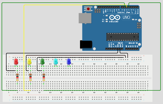
Step 3:Connect the positive leg of the second LED to pin 5 on the Arduino through a 220Ω resistor. Connect its negative leg to GND.
 .
.
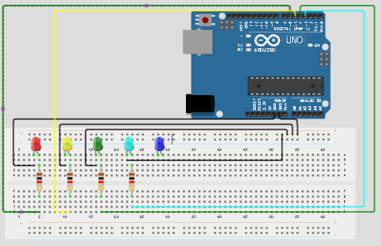
Step 4: Connect the positive leg of the third LED to pin 4 on the Arduino through a 220Ω resistor. Connect its negative leg to GND.
 .
.
Step 5: Connect the positive leg of the fourth LED to pin 3 on the Arduino through a 220Ω resistor. Connect its negative leg to GND.
 .
.
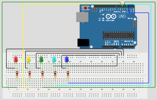
Step 7: Connect the positive leg of the fifth LED to pin 2 on the Arduino through a 220Ω resistor. Connect its negative leg to GND.
 .
.
make sure you connect the arduino usb use blue cable to the Arduino board.
PROGRAMMING
Step 1: Open your Arduino IDE. See how to set up here: Getting Started.
Step 2: Type the following codes in the void setup function as shown in the image below.
``` cpp pinMode(6, OUTPUT); sets pin 6 as an output pin for the first LED. pinMode(5, OUTPUT); sets pin 5 as an output pin for the second LED. pinMode(4, OUTPUT); sets pin 4 as an output pin for the third LED. pinMode(3, OUTPUT); sets pin 3 as an output pin for the fourth LED. pinMode(2, OUTPUT); sets pin 2 as an output pin for the fifth LED.
```
 .
.
NB: pinMode will help the Arduino board to decide which port should be activated. The code below will turn off the three light bulbs.
Step 3: let continue by ting the following codes;
cpp
   digitalWrite(6,HIGH);
   digitalWrite(5,HIGH);
   digitalWrite(4,HIGH);
   digitalWrite(3,HIGH);
   digitalWrite(2,HIGH);
 .
.
Step 4: Save your code. See the Getting Started section
Step 5: Select the arduino board and port See the Getting Started section:Selecting Arduino Board Type and Uploading your code.
Step 6: Upload your code. See the Getting Started section:Selecting Arduino Board Type and Uploading your code
CONCLUSION
This project helps learners understand how to control five LEDs using Arduino. It is a simple introduction to room lighting, multiple outputs, and synchronized LED control.