Project 2.7.1: Smart lightening system with RGB module.
| Description | Learn how to use an ultrasonic sensor with an RGB LED module and an Arduino Uno to create a smart lighting system. The RGB LED changes colour when an object is detected within a specified distance. |
|---|---|
| Use case | Smart parking indicators, automatic decorative lighting, proximity warning systems, interactive displays, and smart home lighting applications. |
Components (Things You will need)
 |
 |
 |
 |
 |
 |
|---|---|---|---|---|---|
Building the circuit
Things Needed:
- Arduino Uno = 1
- Arduino USB cable = 1
- Jumper wires
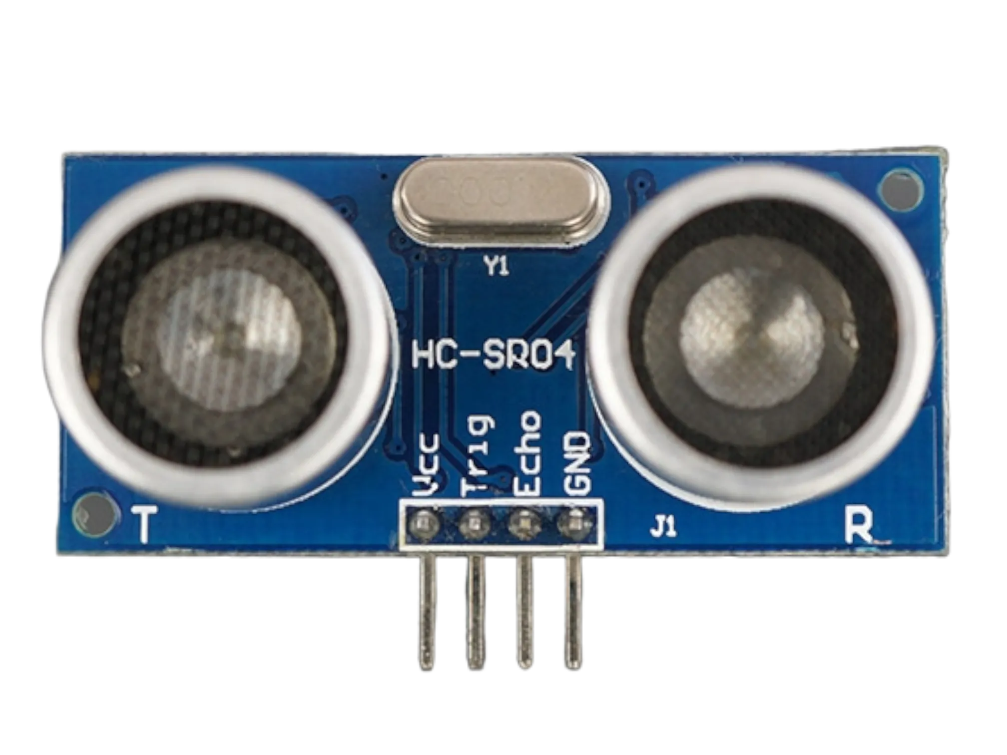
- ultrasonic Sensor = 1
- Breadboard = 1
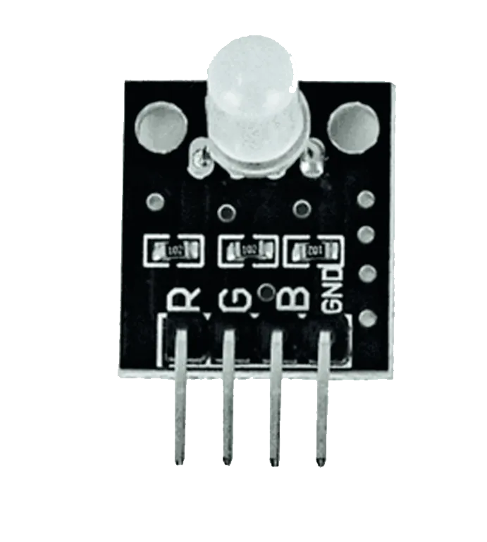
- RGB Module = 1
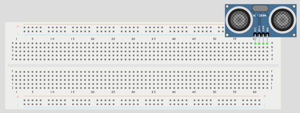
Mounting the component on the breadboard
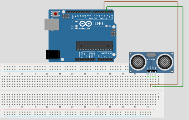
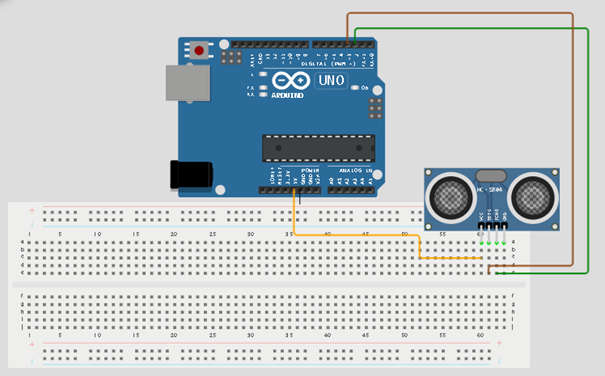
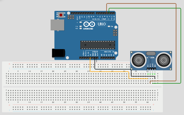
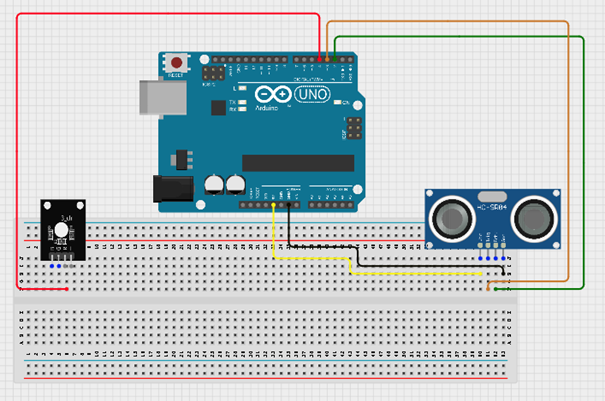
Step 1: Place the ultrasonic sensor on the breadboard.
 .
.
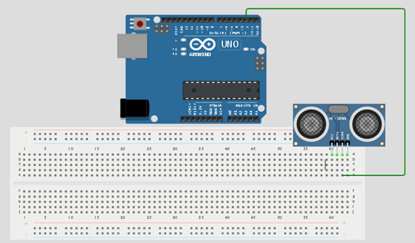
Step 2: Connect the Echo pin of the ultrasonic sensor to pin 2 on the Arduino Uno.
 .
.
Step 3: Connect the Trig pin of the ultrasonic sensor to pin 3 on the Arduino Uno.
 .
.
NB:Take note of the digital pin you allocated to the trig pin.
Step 4: Connect the VCC pin of the ultrasonic sensor to the 5V pin on the Arduino Uno.
 .
.
Step 5: Connect the GND pin of the ultrasonic sensor to GND on the Arduino Uno.
 .
.
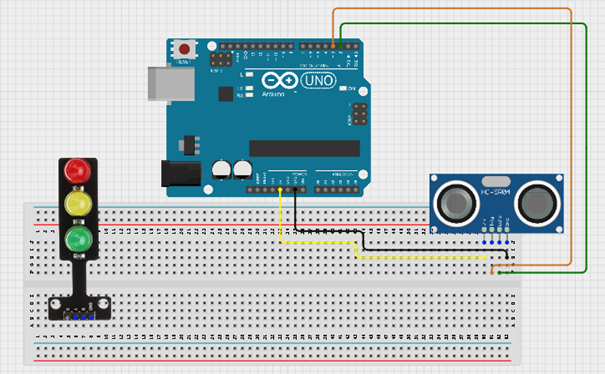
Step 6: Place the RGB module on the breadboard.
 .
.
Step 7: Connect the Red pin of the RGB module to pin 4 on the Arduino Uno.
 .
.
Step 8: Connect the Green pin of the RGB module to pin 5 on the Arduino Uno.
 .
.
Step 9: Connect the Blue pin of the RGB module to pin 6 on the Arduino Uno.
 .
.
Step 10: Connect the GND pin of the RGB module to GND on the Arduino Uno.
 .
.
Step11: After wiring, connect the Arduino Uno to the computer using the USB cable.
PROGRAMMING
Step 1: Open your Arduino IDE. See how to set up here: Getting Started.
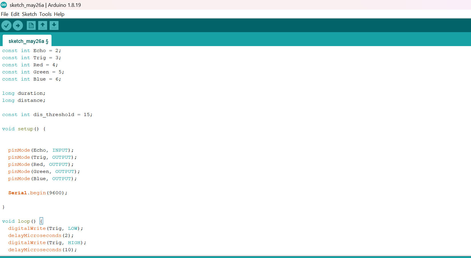
Step 2: Type const int Echo = 2; on line one before void Setup() function.
Step 3: Type int Trig = 3; on line one before void Setup() function.
Step 4: Type int Red = 4; on line one before void Setup() function.
Step 5: Type int Green = 5; on line one before void Setup() function.
Step 6: Type int Blue = 6; on line one before void Setup() function.
Step 7: Type long duration; and Type long distance; on line one before void Setup() function.
Step 8: Type
const int dis_threshold = 15;on line one before void Setup() function.
Step 9:Inside the void loop() function, type the following code:
pinMode (Echo, INTPUT);
pinMode (Trig, OUTPUT);
Serial.begin (9600);
pinMode (Red, OUTPUT);
pinMode (Yellow, OUTPUT);
pinMode (Green, OUTPUT);
Step 10:Inside the loop() function, type the following code:
digitalWrite (Trig, LOW);
delay (2);
digitalWrite (Trig, HIGH);
delay (10);
digitalWrite (Trig, LOW);
duration = pulseIn (Echo, HIGH);
distance = duration * 0.034/2;
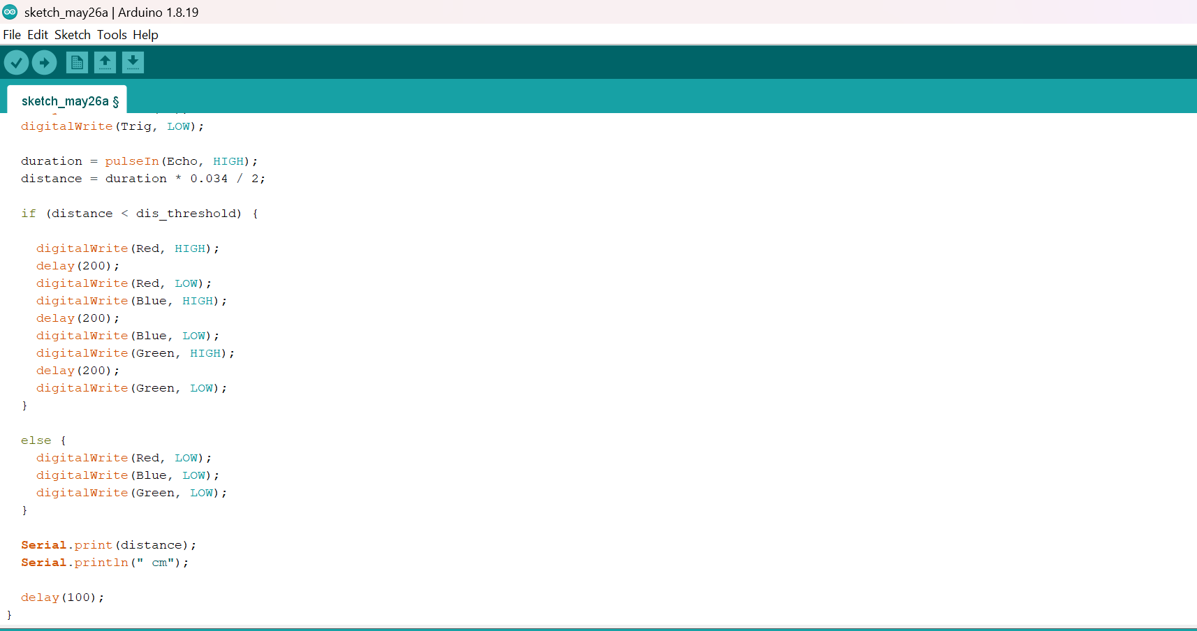
Step 11: Type This Function as shown in the image below.
if (distance < dis_threshold) {
digitalWrite (Red, HIGH);
delay(200)
digitalWrite (Red, LOW);
delay(200)
digitalWrite (Blue, HIGH);
delay(200)
digitalWrite (Blue, LOW);
delay(200)
digitalWrite (Green, HIGH);
delay(200)
digitalWrite (Green, LOW);
else{
digitalWrite (Red, LOW);
digitalWrite (Blue, LOW);
digitalWrite (Green, LOW);
}
Serial.print (distance);
Serial.println (“cm”);
delay (100);
distance = duration * 0.034/2;}
 .
.
 .
.
Step 12: Save your code. See the Getting Started section
Step 13: Select the arduino board and port See the Getting Started section:Selecting Arduino Board Type and Uploading your code.
Step 14: Upload your code. See the Getting Started section:Selecting Arduino Board Type and Uploading your code
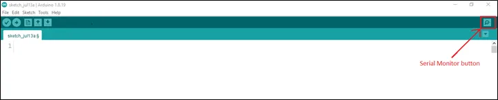
Step 15: Click on the serial monitor icon to view the amount of sound being recorded.
OBSERVATION
Open the Serial Monitor to view the measured distance.
When an object moves within 15 cm of the ultrasonic sensor, the RGB module cycles through the red, blue, and green colours. When no object is detected within the threshold distance, all LEDs remain off.
CONCLUSION
You have successfully built a smart lighting system using an ultrasonic sensor and an RGB module.
In this project, you learned how to:
- Measure distance using an ultrasonic sensor.
- Read sensor values with an Arduino Uno.
- Control multiple LEDs using digital output pins.
- Use conditional statements (
if...else) to make decisions based on sensor input.
This project demonstrates how sensors can be combined with lighting systems to create interactive and automated electronic applications such as smart parking indicators, proximity alarms, and smart home lighting.