Project 1.3.3: TRI-LIGHT
| Description | This project shows how to control three LEDs using a push button with an Arduino Uno. When the button is pressed, all three LEDs turn on together. When the button is released, all the LEDs turn off. |
|---|---|
| Use case | This project can be used as a decorative lighting system, signal indicator, or simple party light display. |
Components (Tools You Will Need)
 |
 |
 |
 |
 |
 |
|---|---|---|---|---|---|
Building The Circuit
Tools Needed:
- Arduino Uno = 1
- Arduino USB cable = 1
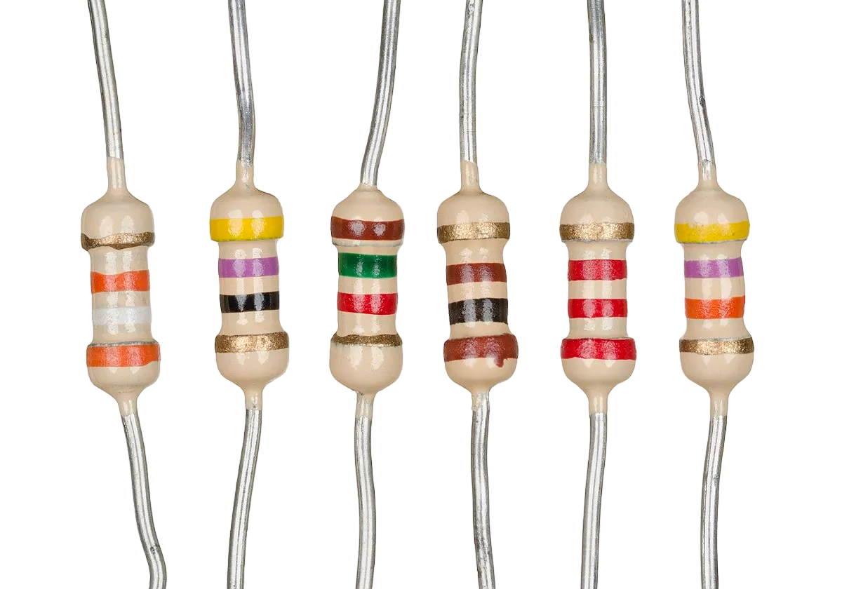
- Resistor = 3
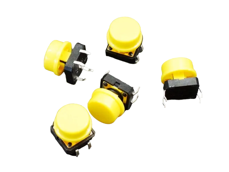
- Push button = 1
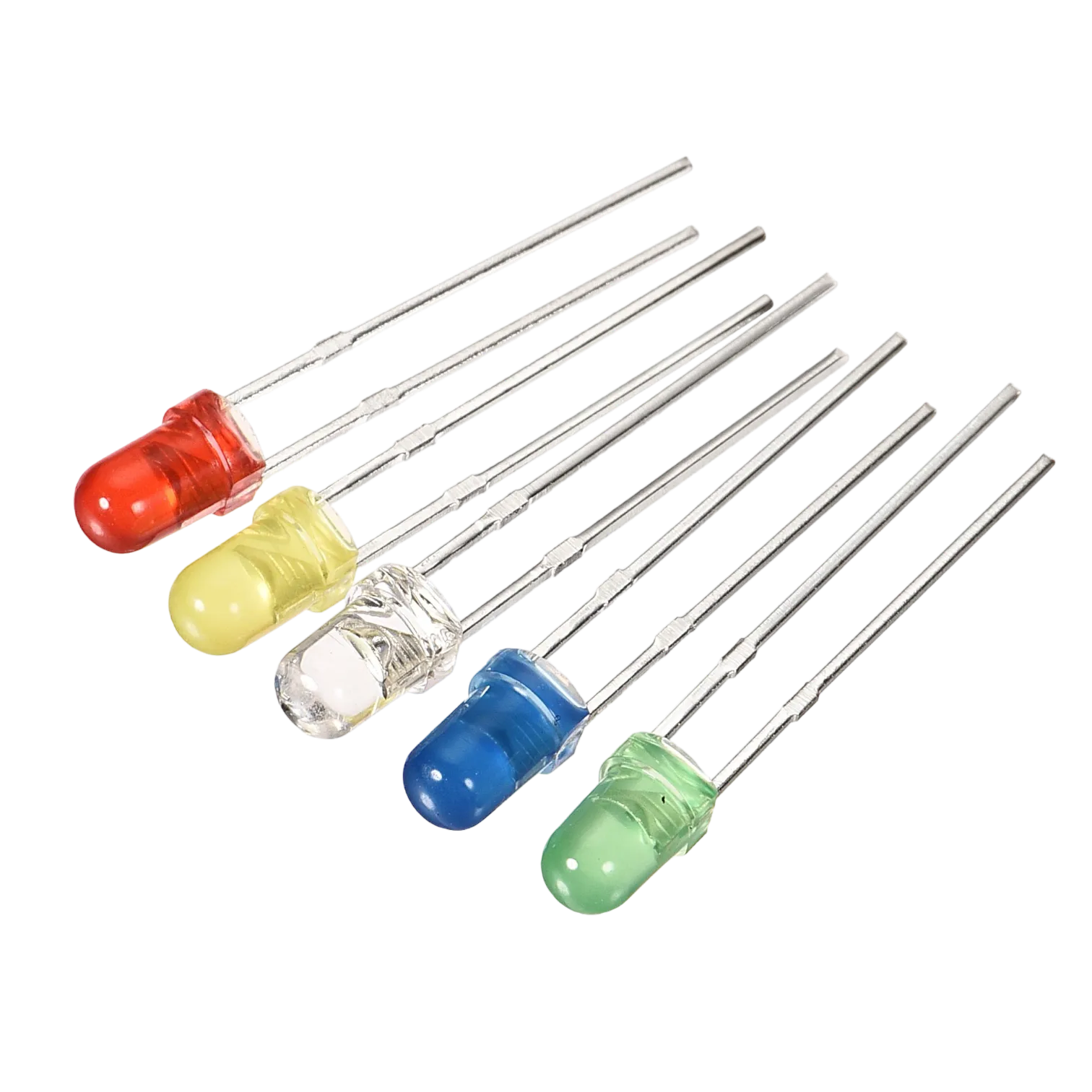
- LEDs = 3
- Jumper Wires
- Breadboard = 1
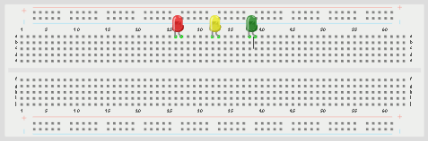
Mounting the component on the breadboard
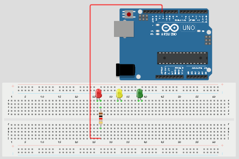
Step 1: Place the three LEDs on the breadboard. The longer legs are the positive pins, while the shorter legs are the negative pins.
 .
.
Step 2: Connect the positive leg of the first LED to pin 12 on the Arduino through a 220Ω resistor.
 .
.
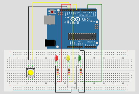
WIRING THE CIRCUIT
Step 3: Connect the positive leg of the second LED to pin 9 on the Arduino through a 220Ω resistor.
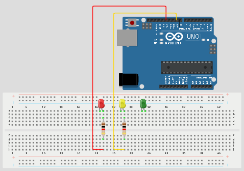
Step 4: Connect the positive leg of the third LED to pin 4 on the Arduino through a 220Ω resistor.
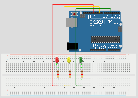
Step 5: Connect one jumper wire from the negative rail of the breadboard to the GND pin on the Arduino Uno. Then connect the negative legs of all the LEDs to the negative rail of the breadboard.
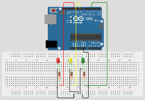
Step 6:Place the push button on the breadboard.
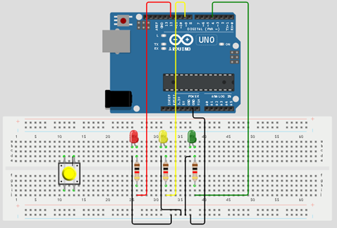
Step 5: Connect one side of the push button to GND on the Arduino Uno.
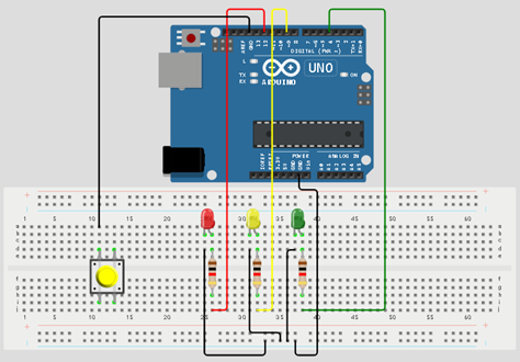
Step 6: Connect the other side of the push button to pin 13 on the Arduino Uno.
Make sure to connect the Arduino USB blue cable to the Arduino board.
PROGRAMMING
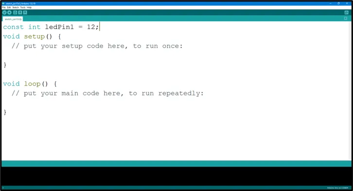
Step 1: Open your Arduino IDE. See how to set up here: Getting Started.
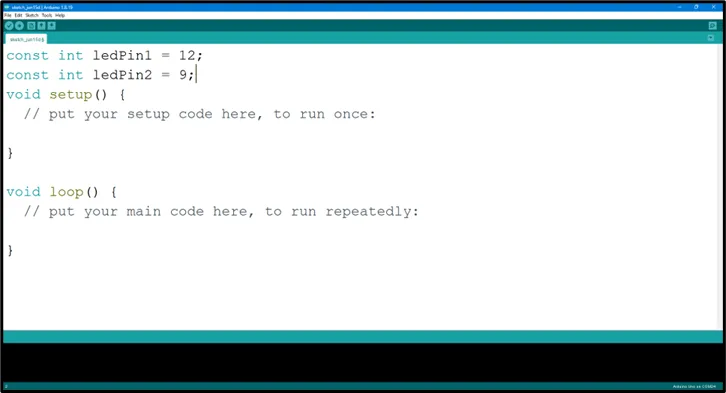
Step 2: Type const int ledPin1 = 12; as shown in the picture below.
 .
.
Step 3: Type const int ledPin2 = 9; as shown in the picture below.
 .
.
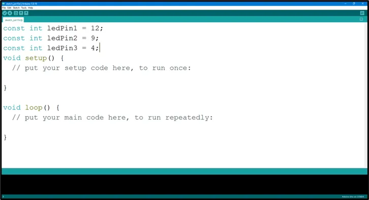
Step 4: Type const int ledPin3 = 4; as shown in the picture below.
 .
.
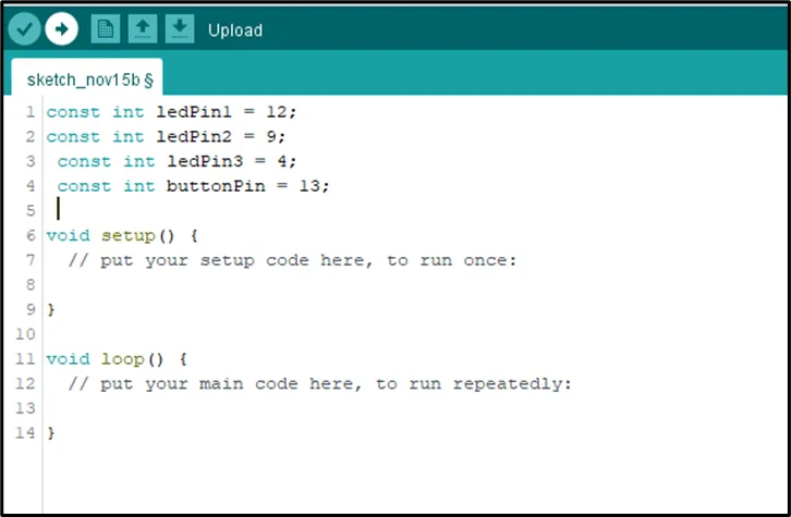
Step 5: Type const int buttonPin = 13; as shown in the picture below.
 .
.
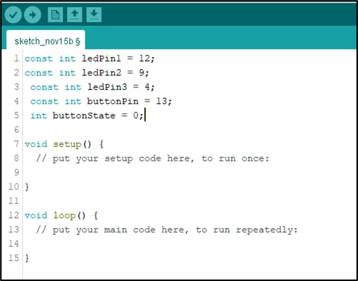
Step 6: Type int buttonState = 0; as shown in the picture below.
 .
.
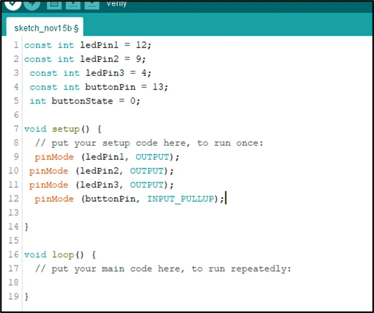
Step 7: Inside the (void setup()), Type
cpp
    pinMode (ledPin1, OUTPUT);
    pinMode (ledPin2, OUTPUT);
    pinMode (ledPin3, OUTPUT);
    pinMode (buttonPin INPUT_PULLUP) ;
as shown in the picture below.
 .
.
NB: pinMode will help the Arduino board to decide which port should be activated.
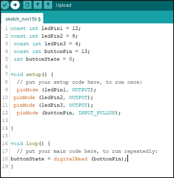
Step 8: Type buttonState = digitalRead (buttonPin); as shown in the picture below.
 .
.
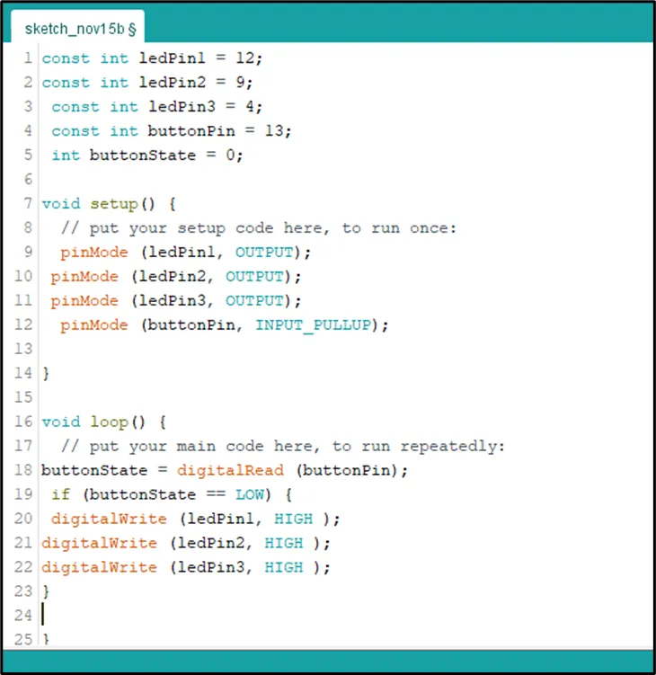
Step 9: Type
 if (buttonState == LOW)
{    digitalWrite (ledPin1,  HIGH) ;
     digitalWrite (ledPin2, HIGH);
     digitalWrite (ledPin3, HIGH);
     digitalWrite (ledPin3, HIGH); }
as shown in the picture below.
 .
.
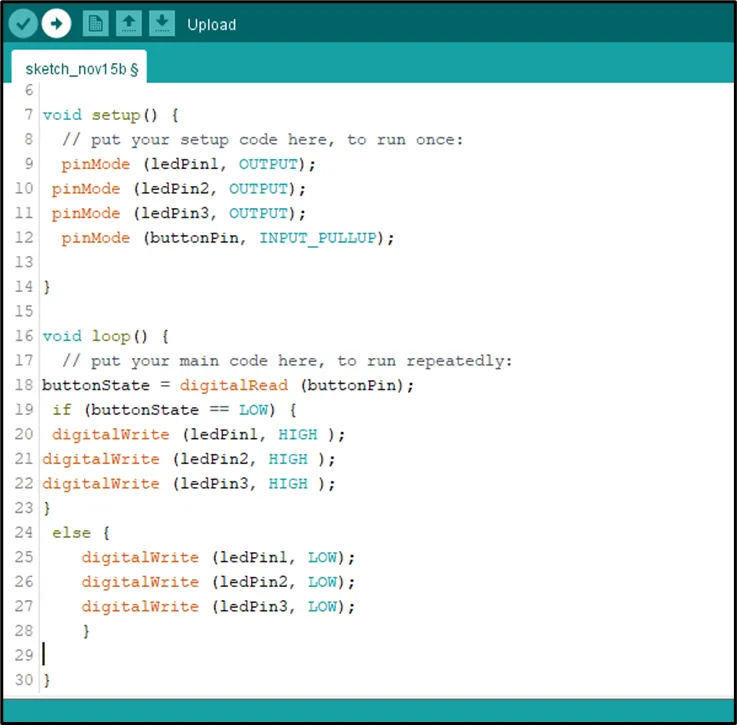
Step 10: Type
cpp
    else {  digitalWrite (ledPin1,  LOW) ;
     digitalWrite (ledPin2, LOW);
     digitalWrite (ledPin3, LOW);
     digitalWrite (ledPin3, HIGH); }
as shown in the picture below.
 .
.
CONCLUSION
This project helps learners understand how to control multiple LEDs using a push button with Arduino. It introduces input devices, output devices, and simple control logic in programming.