Project 1.11.1:Solar-Simulation Night/Day Light
| Description | This project uses an RGB LED to simulate a complete day-and-night cycle. The LED gradually changes colours to represent sunrise, daylight, sunset, and nighttime, creating a visual demonstration of how natural lighting changes throughout the day. |
|---|---|
| Use case | Smart lighting systems, mood lighting, day-night simulation, STEM demonstrations of natural light cycles. |
Components (Things You will need)
 |
 |
 |
 |
 |
|---|---|---|---|---|
Things Needed:
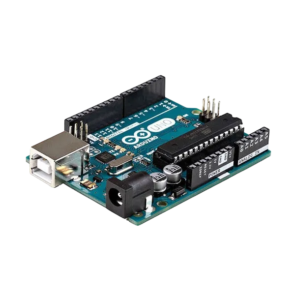
- Arduino Uno = 1
- Arduino USB cable = 1
- Sound sensor = 1
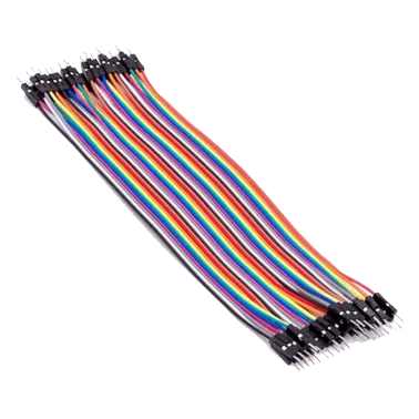
- Jumper Wires
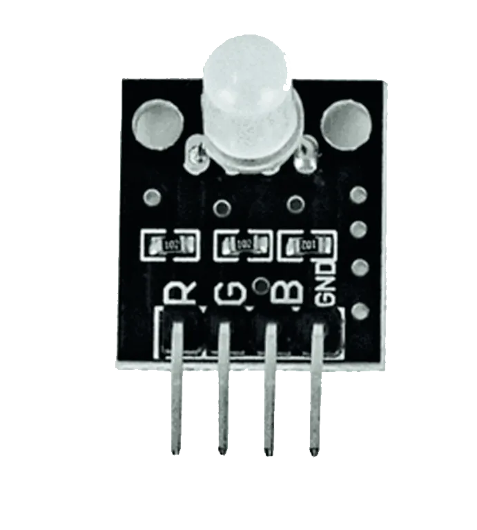
- RGB = 1
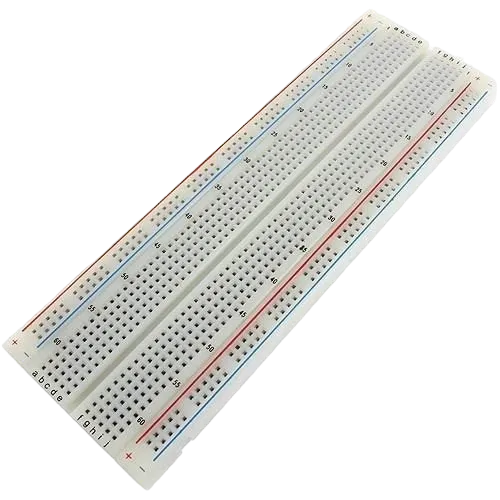
- Breadboard = 1
Mounting the component on the breadboard
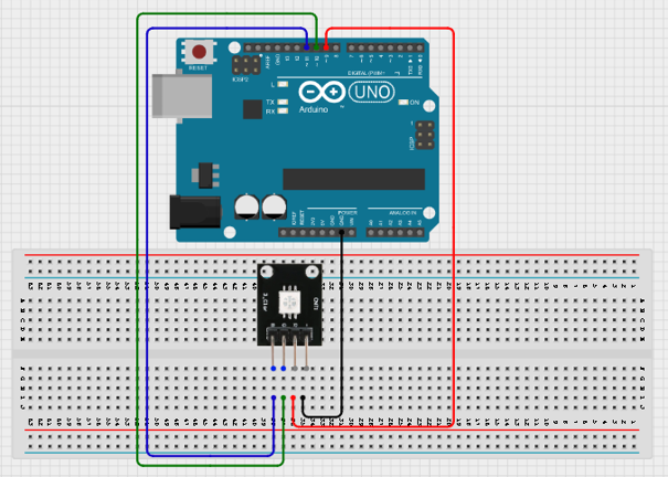
Step 1: Place the RGB LED on the breadboard. Connect the red pin to Pin 9, the green pin to Pin 10, the blue pin to Pin 11, and the common cathode (−) to GND on the Arduino.
 .
.
Step 2: After completing the wiring, connect the Arduino Uno to the computer using the USB cable.
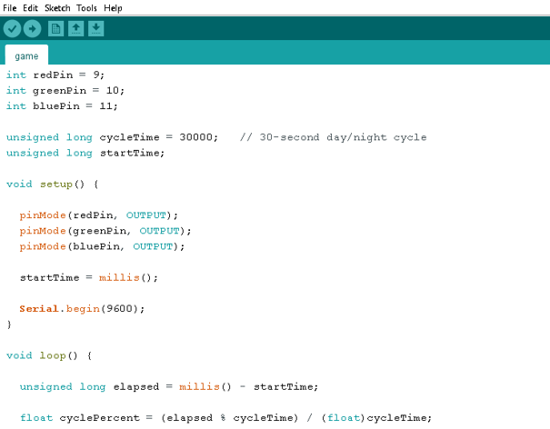
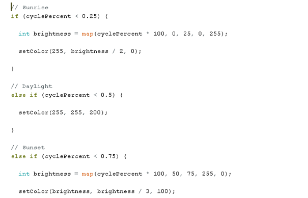
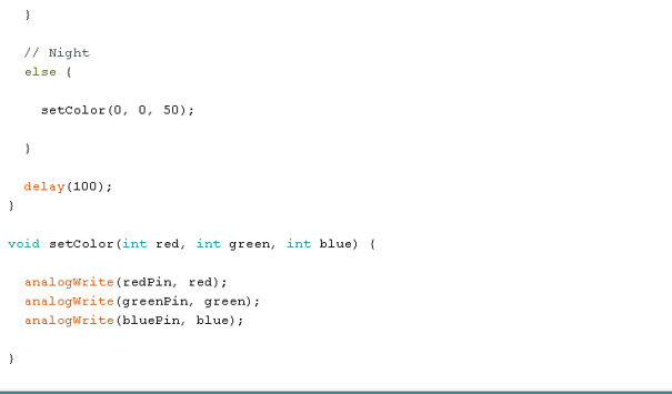
PROGRAMMING
Step 1: Open your Arduino IDE. See how to set up here: Getting Started.
 .
.
 .
.
 .
.
Uploading the code
Step 1: Save your code. See the Getting Started section
Step 2: Select the arduino board and port See the Getting Started section:Selecting Arduino Board Type and Uploading your code.
Step 3: Upload your code. See the Getting Started section:Selecting Arduino Board Type and Uploading your code
OBERVATION
- The RGB LED starts with a sunrise effect.
- The colour gradually changes to bright daylight.
- The LED transitions into sunset colours.
- A dim blue light represents nighttime.
- The cycle continuously repeats every 30 seconds.
CONCLUSION
This project demonstrates analog sensor reading, threshold This project demonstrates RGB LED colour mixing, PWM control, time-based automation, and natural light simulation. It provides a simple introduction to creating realistic lighting effects and understanding how colour transitions can be programmed using Arduino.