Project 2.11.9: Clap Sensitivity Dial
| Description | This project uses a potentiometer to adjust the clap detection threshold of a sound sensor. The Arduino continuously reads the analog output (A0) of the sound sensor and compares it with a threshold set by the potentiometer. When the sound level exceeds the selected threshold, a clap or loud sound is detected and a message is displayed in the Serial Monitor. |
|---|---|
| Use case | This project can be used in voice-activated lighting, smart home controls, noise-triggered alarms, and interactive installations, where the sound detection sensitivity can be adjusted to suit different environments. |
Components (Things You will need)
 |
 |
 |
 |
 |
 |
|---|---|---|---|---|---|
Building the circuit
Things Needed:
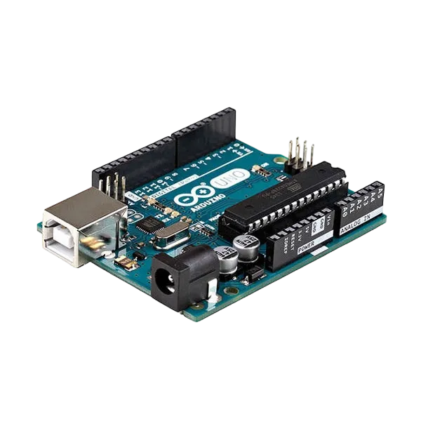
- Arduino Uno = 1
- Arduino USB cable = 1
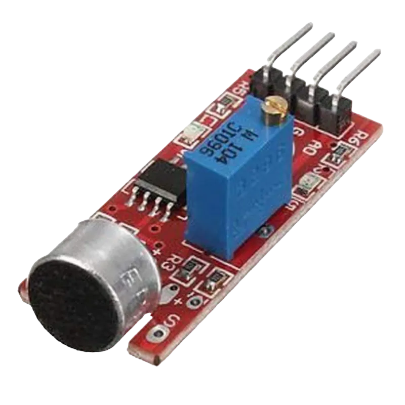
- Sound sensor module = 1
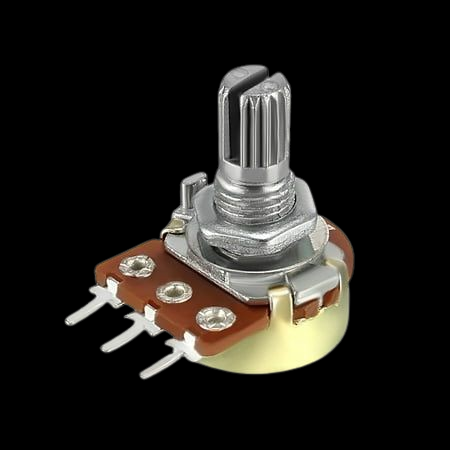
- Potentiometer = 1
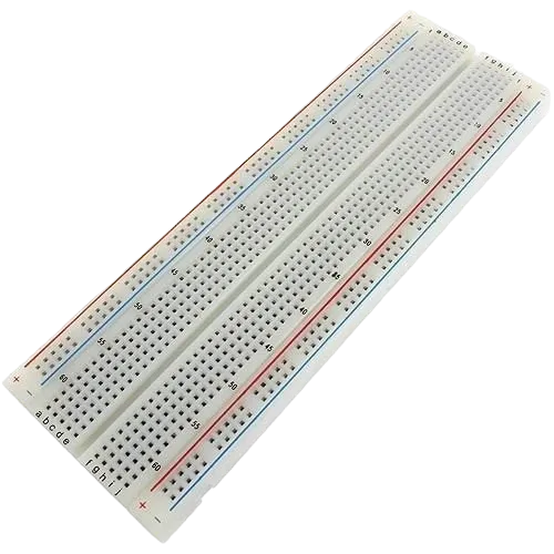
- Breadboard = 1
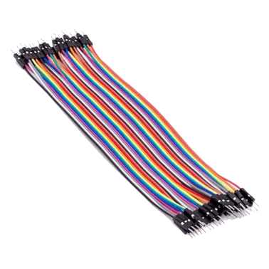
- Jumper wires
Mounting the component on the breadboard
Step 1: Place the Potentiometer and the Sound Sensor on the breadboard.
Both the sound sensor and the potentiometer require 5V and GND. Since the Arduino Uno has only one 5V pin, use the breadboard power rails to distribute power.

NB: Make sure all components are securely placed on the breadboard with correct orientation.
WIRING THE CIRCUIT
Step 2: Connect the A0 pin of the sound sensor to Analog Pin A0 on the Arduino Uno using male-to-male jumper wire.
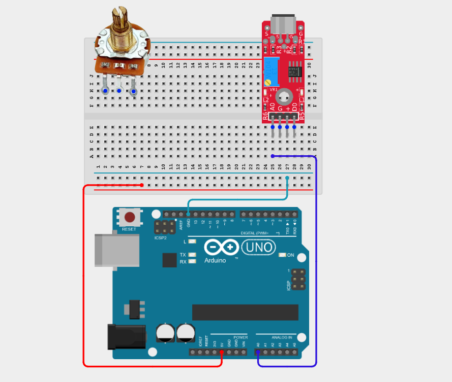
Step 3: Connect the VCC pin of the sound sensor to the positive (+) power rail and the GND pin to the negative (–) power rail on the breadboard using male-to-male jumper wires.

Step 4: Connect one outer pin of the potentiometer to the positive (+) power rail and the other outer pin to the negative (–) power rail on the breadboard using male-to-male jumper wires.

Step 5: Connect the centre (wiper) pin of the potentiometer to Analog Pin A1 on the Arduino Uno using male-to-male jumper wire.

Make sure to connect the Arduino USB cable to the Arduino board.
PROGRAMMING
Step 1: Open your Arduino IDE. See how to set up here: Getting Started.
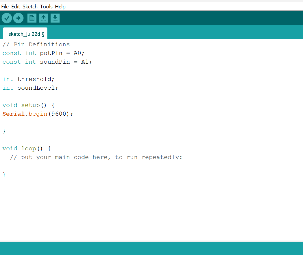
Step 2: Type the following code in your Arduino IDE: const int potPin = A0;, const int soundPin = A1;, int threshold;, int soundLevel; as shown in the image below.

Step 3: Type the following code in your Arduino IDE inside the void setup() function Serial.begin(9600); as shown in the image below.
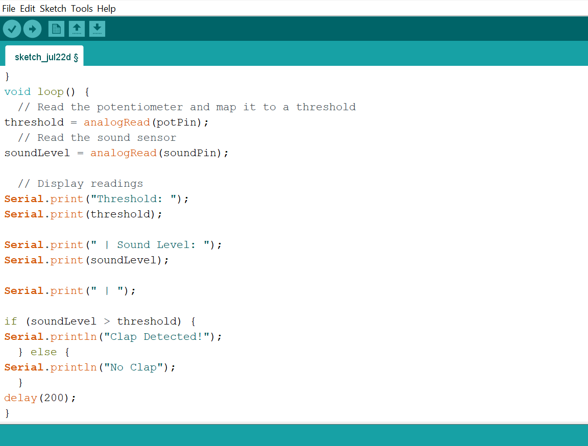
Step 4: Type the following code in your Arduino IDE inside the void loop() function threshold = analogRead(potPin);, soundLevel = analogRead(soundPin);, Serial.print("Threshold: ");, Serial.print(threshold);, Serial.print(" | Sound Level: ");, Serial.print(soundLevel);, Serial.print(" | ");, if (soundLevel > threshold) {, Serial.println("Clap Detected!"); }, else {, Serial.println("No Clap"); }, delay(200); as shown in the image below.
Uploading the code
Step 1: Save your code. See the Getting Started section
Step 2: Select the Arduino board and port. See the Getting Started section
Step 3: Upload your code.
OBSERVATION
Rotating the potentiometer changes the clap detection threshold, allowing the Arduino to detect loud sounds based on the user-selected sensitivity.
CONCLUSION
This project helps learners understand how to combine multiple components with Arduino to create more complex interactive systems and automation solutions.