Project 2.7.7: Multi-Factor Tracker
| Description | This project measures both proximity (ultrasonic) and sound levels simultaneously to log environmental events with multiple sensor inputs. |
|---|---|
| Use case | This project can be used in environmental monitoring, security systems, smart buildings, and industrial automation to simultaneously monitor object proximity and sound levels for detecting and logging environmental events. |
Components (Things You will need)
 |
 |
 |
 |
 |
 |
|---|---|---|---|---|---|
Building the circuit
Things Needed:
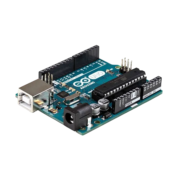
- Arduino Uno = 1
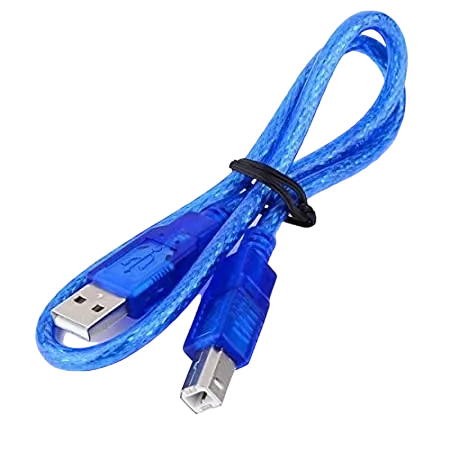
- Arduino USB cable = 1
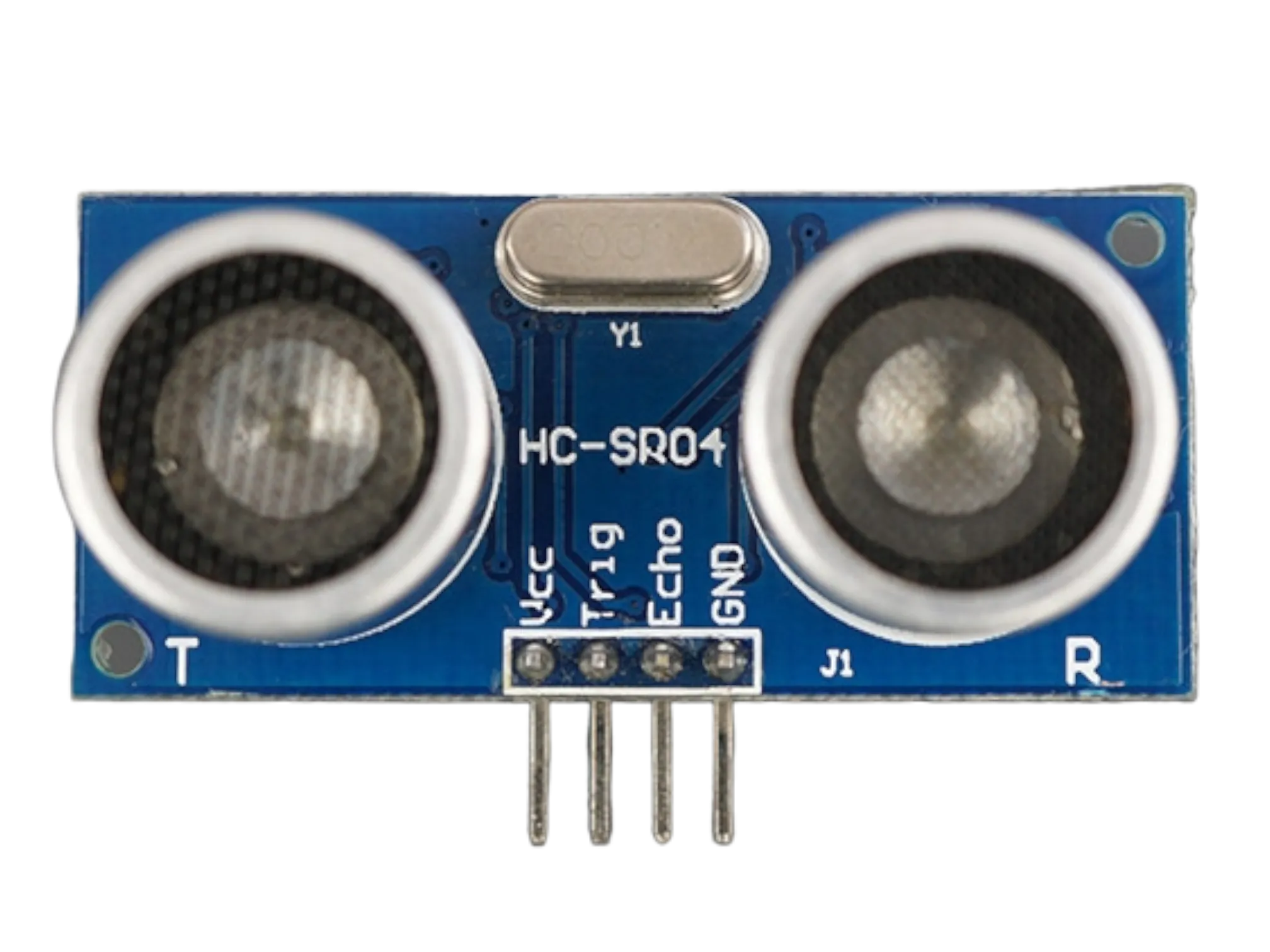
- Ultrasonic sensor = 1
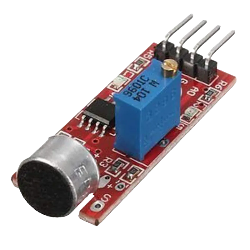
- Sound sensor module = 1
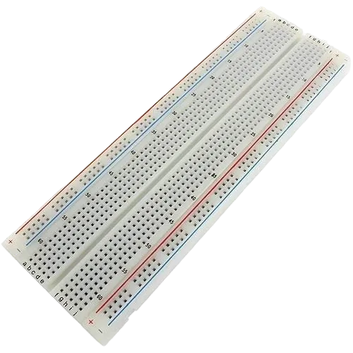
- Breadboard = 1
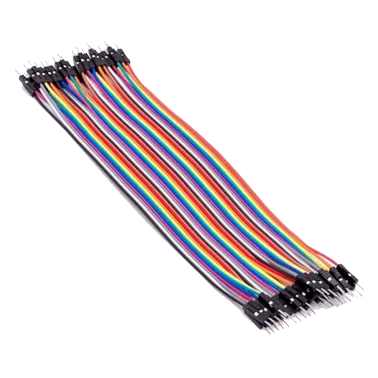
- Jumper wires
Mounting the component on the breadboard
Step 1: Place the Ultrasonic sensor and the Sound sensor module on the breadboard following the circuit diagram.

Both the ultrasonic sensor and the sound sensor module require a 5V power supply. Since the Arduino Uno has only one 5V pin, use the breadboard power rails to distribute power.
NB: Make sure all components are securely placed on the breadboard with correct orientation.
WIRING THE CIRCUIT
Step 2: Connect the VCC pin of the ultrasonic sensor to the positive (+) power rail on the breadboard using male-to-male jumper wire.

Step 3: Connect the GND pin of the ultrasonic sensor to the negative (–) power rail on the breadboard using male-to-male jumper wire.

Step 4: Connect the TRIG pin of the ultrasonic sensor to Digital Pin 9 on the Arduino Uno using male-to-male jumper wire.

Step 5: Connect the ECHO pin of the ultrasonic sensor to Digital Pin 10 on the Arduino Uno using male-to-male jumper wire.

Step 6: Connect the D0 pin of the sound sensor to Digital Pin 3 on the Arduino Uno using male-to-male jumper wire.

Step 7: Connect the VCC pin of the sound sensor to the positive (+) power rail and the GND pin of the sound sensor to the negative (–) power rail on the breadboard using male-to-male jumper wires.

Make sure to connect the Arduino USB cable to the Arduino board.
PROGRAMMING
Step 1: Open your Arduino IDE. See how to set up here: Getting Started.
Step 2: Type the following code in your Arduino IDE: const int trigPin = 9;, const int echoPin = 10;, const int soundPin = 3;, long duration;, float distance; as shown in the image below.

Step 3: Type the following code in your Arduino IDE inside the void setup() function: pinMode(trigPin, OUTPUT);, pinMode(echoPin, INPUT);, pinMode(soundPin, INPUT);, Serial.begin(9600); as shown in the image below.

Step 4: Type the following code in your Arduino IDE inside the void loop() function: digitalWrite(trigPin, LOW);, delayMicroseconds(2);, digitalWrite(trigPin, HIGH);, delayMicroseconds(10);, digitalWrite(trigPin, LOW);, duration = pulseIn(echoPin, HIGH);,distance = duration * 0.0343 / 2;, bool soundDetected = (digitalRead(soundPin) == LOW);, Serial.print("Distance: ");, Serial.print(distance);, Serial.print(" cm");, Serial.print(" | Sound: ");, if (soundDetected) {, Serial.println("Detected"); }, else {, Serial.println("Not Detected"); }, delay(500); as shown in the image below.

Uploading the code
Step 1: Save your code. See the Getting Started section
Step 2: Select the Arduino board and port. See the Getting Started section
Step 3: Upload your code.
OBSERVATION
The Arduino continuously measures the distance to nearby objects while simultaneously detecting and logging loud sound events in the Serial Monitor.
CONCLUSION
This project helps learners understand how to combine multiple components with Arduino to create more complex interactive systems and automation solutions.