Project 3.11.1: Smart Thermostat Simulator
| Description | Learn how to simulate a smart thermostat using an LDR module, servo motor, RGB LED, and push button. The LDR estimates a heat index based on light intensity, automatically controlling a ventilation flap while the push button provides manual override. |
|---|---|
| Use case | This project can be applied in smart home ventilation systems, automated greenhouse climate control, HVAC demonstrations, classroom simulations, and intelligent environmental monitoring. |
Components (Things You will need)
 |
 |
 |
 |
 |
 |
 |
 |
|---|---|---|---|---|---|---|---|
Building the circuit
Things Needed:
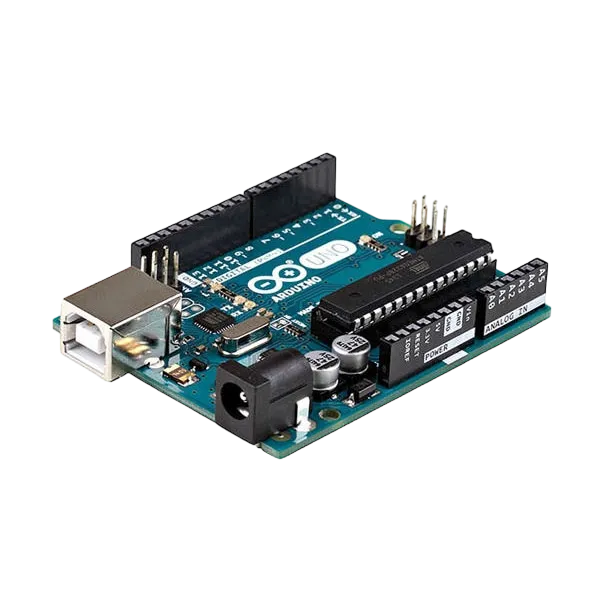
- Arduino Uno = 1
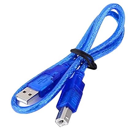
- Arduino USB cable = 1
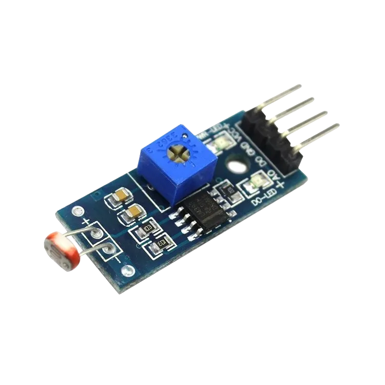
- LDR module = 1
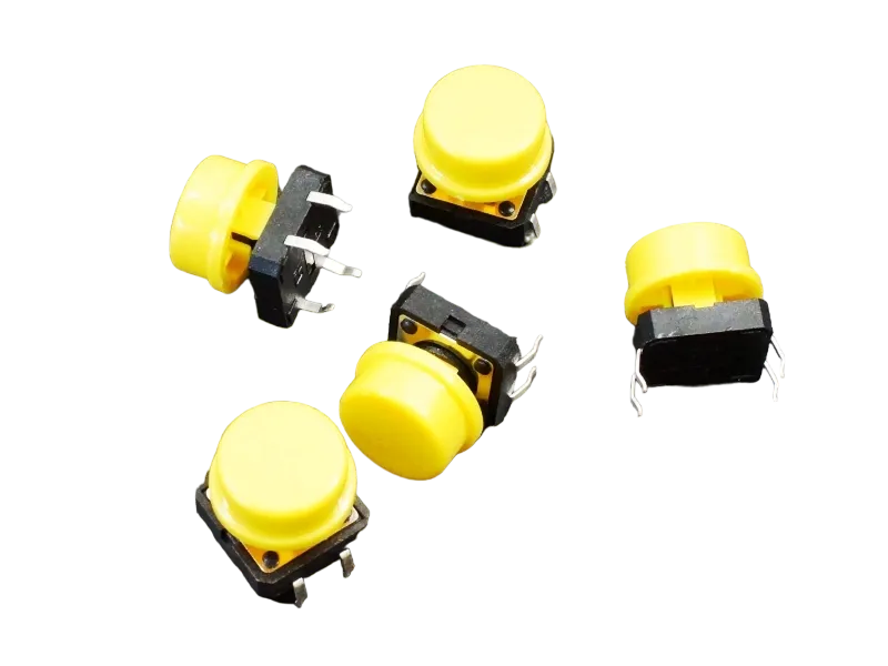
- Push button = 1
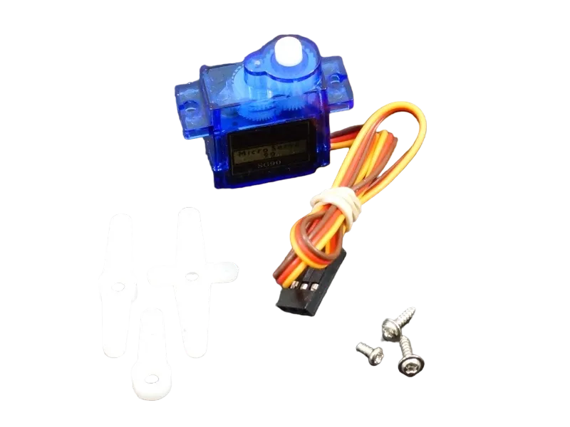
- Servo motor = 1
- RGB LED module = 1
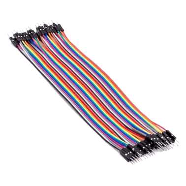
- Jumper Wires
Mounting the component on the breadboard
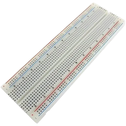
Step 1:Carefully mount the LDR Module, Push Button, Servo Motor, RGB LED, and 220 Ω resistors (for the RGB LED) on the breadboard, ensuring the components are spaced appropriately to allow for neat wiring and easier troubleshooting.
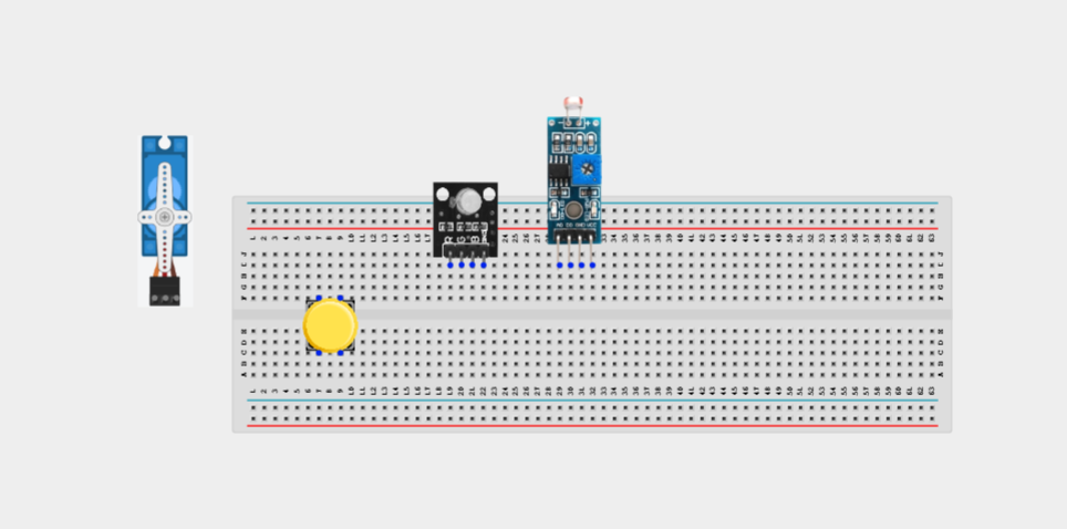
NB: For complex circuits, plan your component placement to minimize wire crossing and ensure clean connections.
WIRING THE CIRCUIT
Step 2:onnect the 5V pin on the Arduino Uno to the positive (+) power rail on the breadboard and the GND pin to the negative (-) power rail. This provides a common power supply for all the components connected to the breadboard.
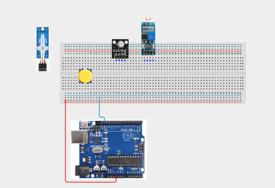
Step 3: Connect the LDR Module to the Arduino Uno by connecting the VCC pin to the positive (+) power rail on the breadboard, the GND pin to the negative (-) power rail, and the OUT pin to Analog Pin A0 on the Arduino.
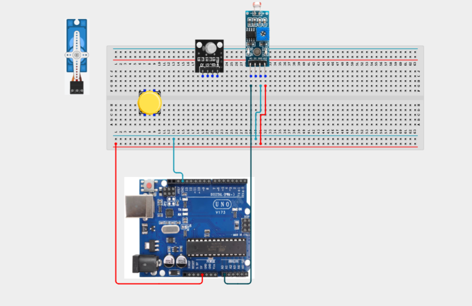
Step 4: Connect the Push Button to the Arduino Uno by connecting one terminal of the button to Digital Pin 2 and the opposite terminal to the GND rail on the breadboard.
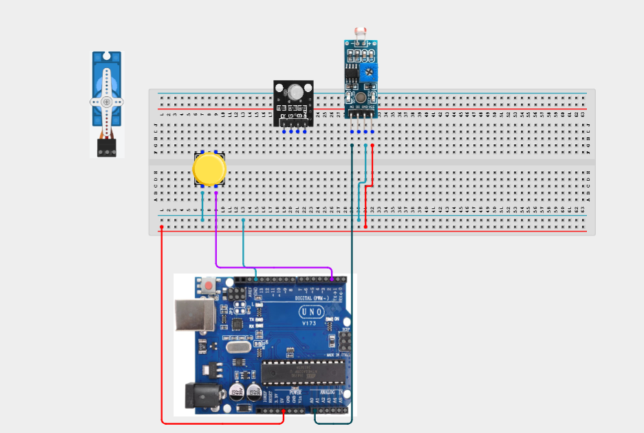
Step 5:Connect the Servo Motor to the Arduino Uno by connecting the Red (VCC) wire to the positive (+) power rail on the breadboard, the Brown/Black (GND) wire to the negative (-) power rail, and the Orange/Yellow (Signal) wire to Digital Pin 9 on the Arduino
Note: If the servo behaves erratically, use an external regulated 5V power supply and connect its ground to the Arduino GND.
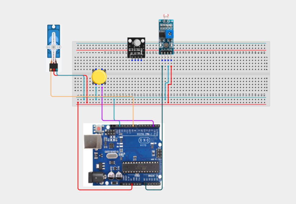
Step 6: Connect the RGB LED Module to the Arduino Uno by connecting the GND pin to the negative (-) power rail on the breadboard, the Red signal pin to Digital Pin 3, the Green signal pin to Digital Pin 5, and the Blue signal pin to Digital Pin 6.
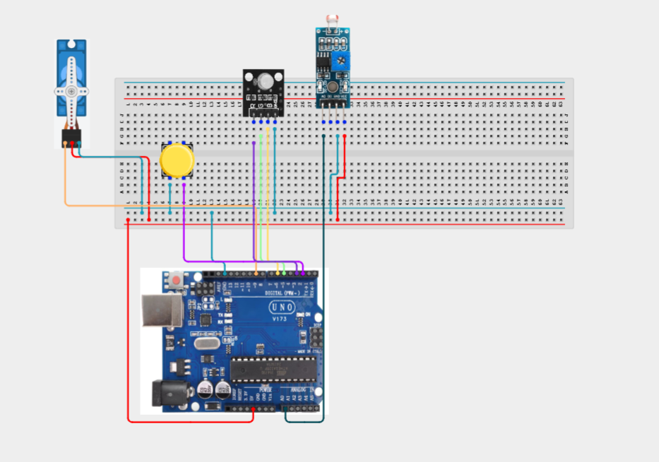
Make sure to connect the Arduino USB cable to the Arduino board.
PROGRAMMING
Step 1: Open your Arduino IDE. See how to set up here: Getting Started.
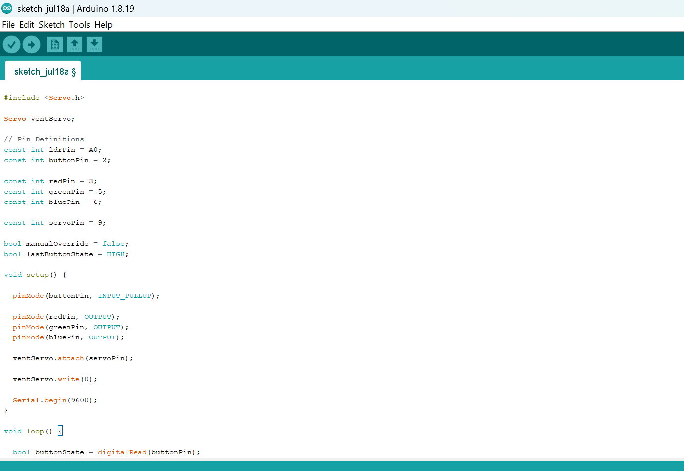
Step 2: Write the complete program implementing the system logic with appropriate pin definitions, setup configuration, and the main control loop.
#include <Servo.h>

Servo ventServo;

// Pin Definitions
const int ldrPin = A0;
const int buttonPin = 2;

const int redPin = 3;
const int greenPin = 5;
const int bluePin = 6;

const int servoPin = 9;

bool manualOverride = false;
bool lastButtonState = HIGH;

void setup() {

  pinMode(buttonPin, INPUT_PULLUP);

  pinMode(redPin, OUTPUT);
  pinMode(greenPin, OUTPUT);
  pinMode(bluePin, OUTPUT);

  ventServo.attach(servoPin);

  ventServo.write(0);

  Serial.begin(9600);
}

void loop() {

  bool buttonState = digitalRead(buttonPin);

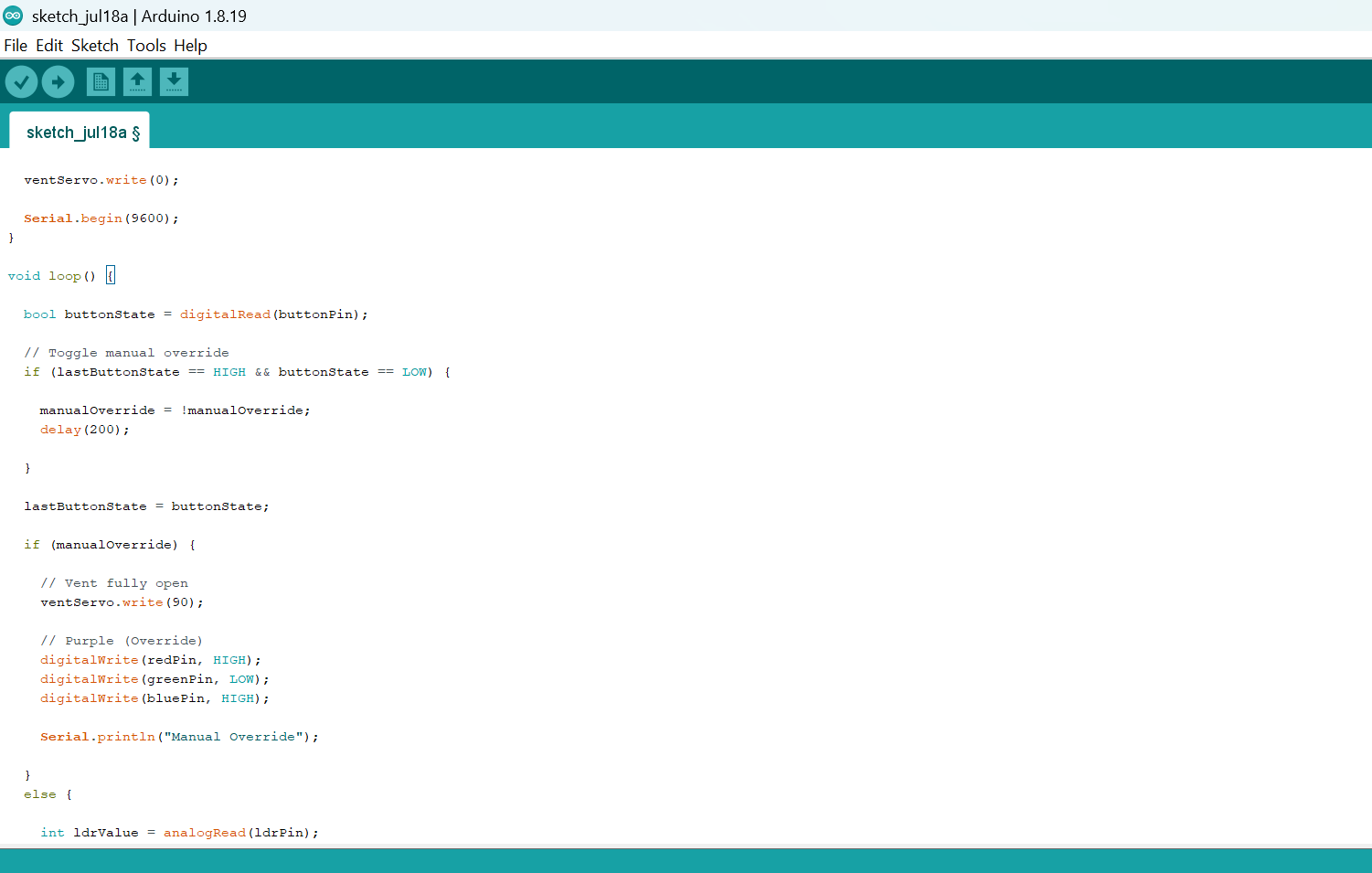
  // Toggle manual override
  if (lastButtonState == HIGH && buttonState == LOW) {

    manualOverride = !manualOverride;
    delay(200);

  }

  lastButtonState = buttonState;

  if (manualOverride) {

    // Vent fully open
    ventServo.write(90);

    // Purple (Override)
    digitalWrite(redPin, HIGH);
    digitalWrite(greenPin, LOW);
    digitalWrite(bluePin, HIGH);

    Serial.println("Manual Override");

  }
  else {

    int ldrValue = analogRead(ldrPin);

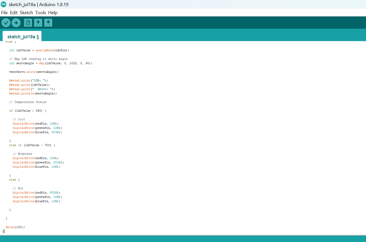
    // Map LDR reading to servo angle
    int servoAngle = map(ldrValue, 0, 1023, 0, 90);

    ventServo.write(servoAngle);

    Serial.print("LDR: ");
    Serial.print(ldrValue);
    Serial.print("  Servo: ");
    Serial.println(servoAngle);

    // Temperature Status

    if (ldrValue < 350) {

      // Cool
      digitalWrite(redPin, LOW);
      digitalWrite(greenPin, LOW);
      digitalWrite(bluePin, HIGH);

    }
    else if (ldrValue < 700) {

      // Moderate
      digitalWrite(redPin, LOW);
      digitalWrite(greenPin, HIGH);
      digitalWrite(bluePin, LOW);

    }
    else {

      // Hot
      digitalWrite(redPin, HIGH);
      digitalWrite(greenPin, LOW);
      digitalWrite(bluePin, LOW);

    }

  }

  delay(100);
}
Step 7: Save your code. See the Getting Started section
Step 8: Select the arduino board and port See the Getting Started section:Selecting Arduino Board Type and Uploading your code.
Step 9: Upload your code. See the Getting Started section:Selecting Arduino Board Type and Uploading your code
CONCLUSION
This project demonstrates how sensor inputs, actuator control, and manual user interaction can be combined to create a simple smart thermostat simulator. It reinforces concepts such as analog sensing, servo motor control, digital inputs, conditional programming, and automation commonly used in intelligent climate control systems.