Project 2.7.5: Manual Trigger Radar
| Description | This project activates ultrasonic distance measurement only when a push button is held down, conserving power and allowing on-demand readings. |
|---|---|
| Use case | This project can be used in portable measuring devices, battery-powered systems, field inspection tools, and robotics, where distance measurements are taken only when requested to conserve power and reduce unnecessary sensor operation. |
Components (Things You will need)
 |
 |
 |
 |
 |
 |
|---|---|---|---|---|---|
Building the circuit
Things Needed:
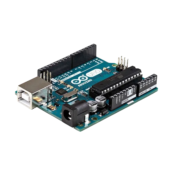
- Arduino Uno = 1
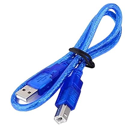
- Arduino USB cable = 1
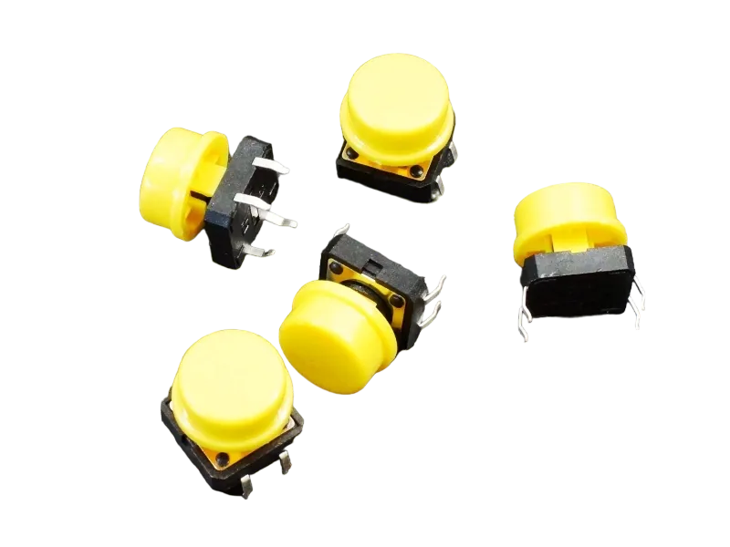
- Push button = 1
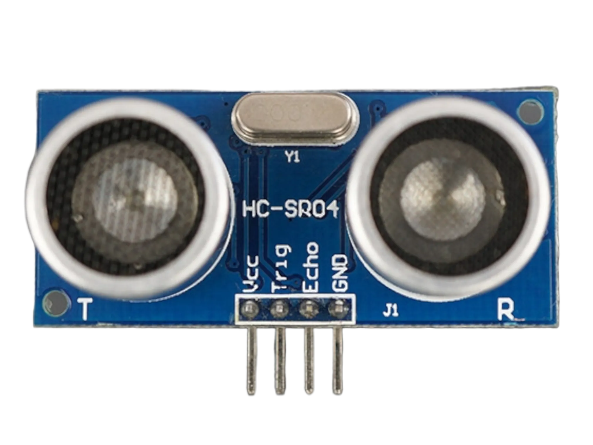
- Ultrasonic sensor = 1
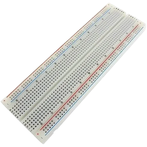
- Breadboard = 1
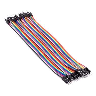
- Jumper wires
Mounting the component on the breadboard
Step 1: Place the Ultrasonic sensor and the Push button on the breadboard.
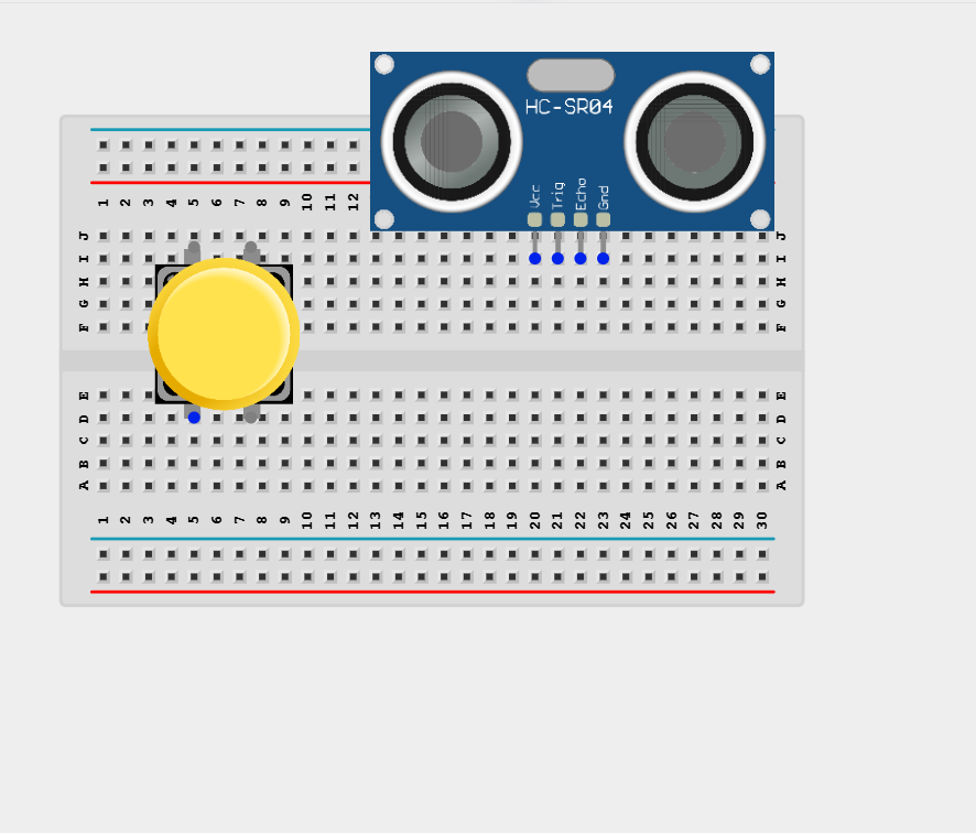
NB: Make sure all components are securely placed on the breadboard with correct orientation.
WIRING THE CIRCUIT
Step 2: Connect the VCC pin of the Ultrasonic Sensor to the Arduino 5V pin the Arduino Uno using male-to-male jumper wire.

Step 3: Connect the GND pin of the Ultrasonic Sensor to the Arduino GND pin the Arduino Uno using male-to-male jumper wire.
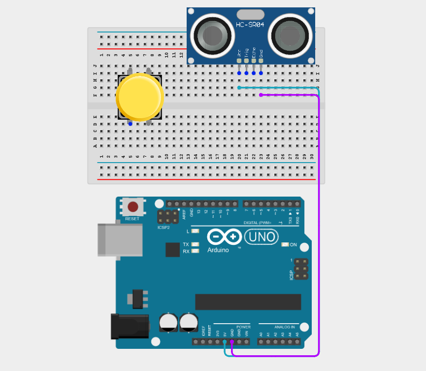
Step 4: Connect the TRIG pin of the Ultrasonic Sensor to the Arduino Digital Pin 9 using a male-to-male jumper wire.

Step 5: Connect the ECHO pin of the Ultrasonic Sensor to the Arduino Digital Pin 10 using a male-to-male jumper wire.

Step 6: Connect one terminal of the push button to Digital Pin 2 on the Arduino using a male-to-male jumper wire.
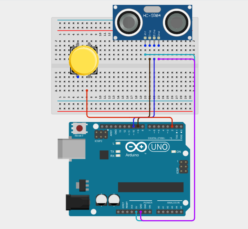
Step 7: Connect the opposite terminal of the push button to GND on the Arduino using a male-to-male jumper wire.

Make sure to connect the Arduino USB cable to the Arduino board.
PROGRAMMING
Step 1: Open your Arduino IDE. See how to set up here: Getting Started.
Step 2: Type the following code in your Arduino IDE: const int trigPin = 9;, const int buttonPin = 2;, long duration;, float distance; as shown in the image below.

Step 3: Type the following code in your Arduino IDE inside the void setup() pinMode(trigPin, OUTPUT);, pinMode(echoPin, INPUT);, pinMode(buttonPin, INPUT_PULLUP);, Serial.begin(9600); as shown in the image below.
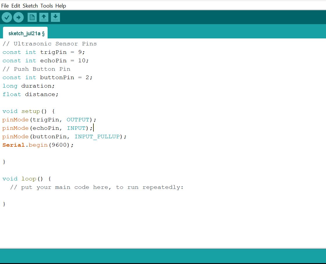
Step 4: Type the following code in your Arduino IDE inside the void loop() if (digitalRead(buttonPin) == LOW) {, digitalWrite(trigPin, LOW);, delayMicroseconds(2);, digitalWrite(trigPin, HIGH);, delayMicroseconds(10);, digitalWrite(trigPin, LOW);, duration = pulseIn(echoPin, HIGH);, distance = duration * 0.0343 / 2;,Serial.print("Distance: ");, Serial.print(distance);, Serial.println(" cm");, delay(100); } as shown in the image below.

Uploading the code
Step 1: Save your code. See the Getting Started section
Step 2: Select the Arduino board and port. See the Getting Started section
Step 3: Upload your code.
The measured distance is displayed continuously in the Serial Monitor while the button is held down.
CONCLUSION
This project helps learners understand how to combine multiple components with Arduino to create more complex interactive systems and automation solutions.