Project 2.5.4: Manual Night Override
| Description | This project uses a push button to override the automatic reading of an LDR, allowing manual control when the automatic light sensing is not desired. |
|---|---|
| Use case | This project can be used in smart lighting systems, home automation, industrial control panels, and energy management systems, where users can manually override automatic light sensing when needed. |
Components (Things You will need)
 |
 |
 |
 |
 |
 |
|---|---|---|---|---|---|
Building the circuit
Things Needed:
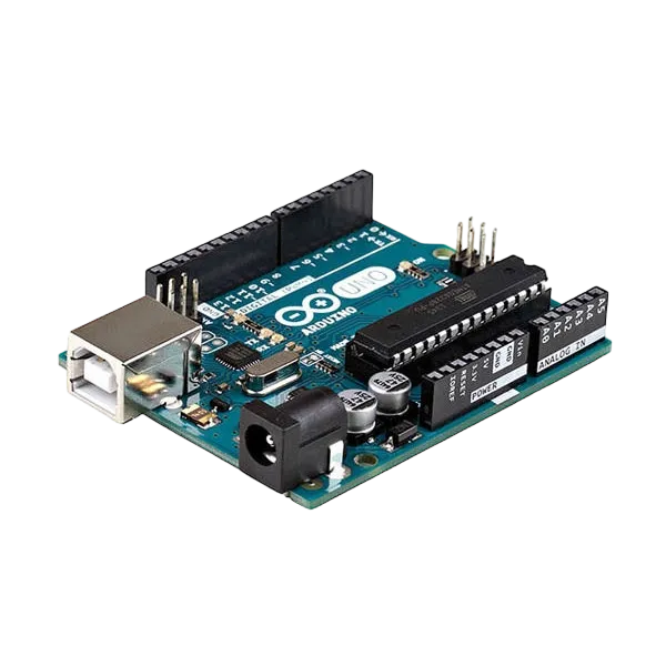
- Arduino Uno = 1
- Arduino USB cable = 1
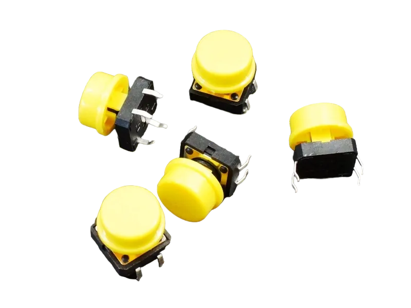
- Push button = 1
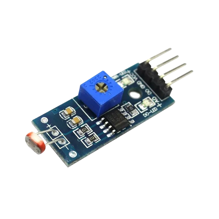
- LDR module = 1
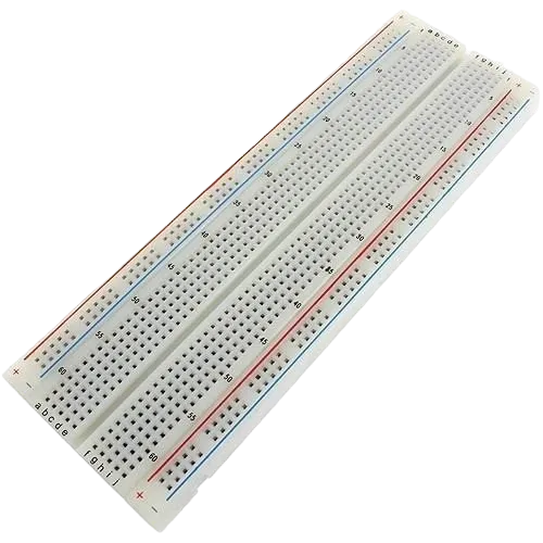
- Breadboard = 1
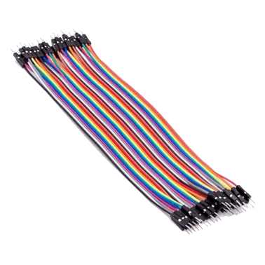
- Jumper wires
Mounting the component on the breadboard
Step 1: Place the LDR module and the Push button on the breadboard.

NB: Make sure all components are securely placed on the breadboard with correct orientation.
WIRING THE CIRCUIT
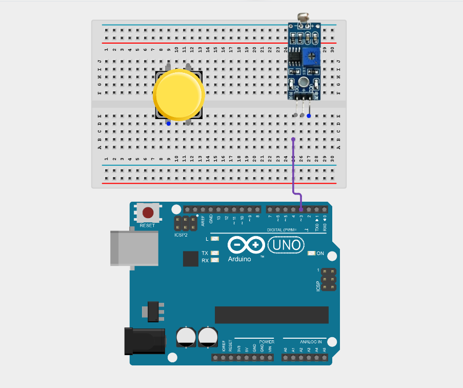
Step 2: Connect the D0 pin of the LDR sensor module to Digital Pin 3 on the Arduino using male-to-male jumper wire.
Step 3: Connect the VCC pin of the LDR sensor module to the Arduino 5V pin using male-to-male jumper wire.

Step 4: Connect the GND or negative (-) pin of the LDR sensor module to the Arduino GND pin using male-to-male jumper wire.

Step 5: Connect one terminal of the push button to Digital Pin 2 on the Arduino using male-to-male jumper wire.
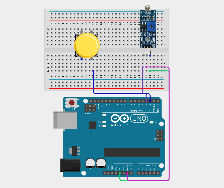
Step 6: Connect one the other terminal of the push button to GND on the Arduino using male-to-male jumper wire.

Make sure to connect the Arduino USB cable to the Arduino board.
PROGRAMMING
Step 1: Open your Arduino IDE. See how to set up here: Getting Started.
Step 2: Type the following code in your Arduino IDE: const int ldrPin = 3;, const int buttonPin = 2;, bool automaticMode = true;, bool lastButtonState = HIGH;,bool currentButtonState; as shown in the image below.

Step 3: Type the following code in your Arduino IDE inside the void setup() function: pinMode(ldrPin, INPUT);, pinMode(buttonPin, INPUT_PULLUP);, Serial.begin(9600);, Serial.println("=== Automatic Light Sensing ===");,Serial.println("Press the button to enable or disable automatic mode."); as shown in the image below.

Step 4: Type the following code in your Arduino IDE inside the void setup() function: currentButtonState = digitalRead(buttonPin);, if (lastButtonState == HIGH && currentButtonState == LOW) { delay(20);, automaticMode = !automaticMode;, if (automaticMode) { Serial.println("Automatic Mode Enabled"); },else { Serial.println("Manual Override Enabled"); } }, lastButtonState = currentButtonState;, if (automaticMode) { int lightState = digitalRead(ldrPin);, if (lightState == LOW) { Serial.println("Dark Environment Detected"); }, else { Serial.println("Bright Environment Detected");} }, else, { Serial.println("Automatic Light Sensing Disabled"); }, delay(500); as shown in the image below.

Uploading the code
Step 1: Save your code. See the Getting Started section
Step 2: Select the Arduino board and port. See the Getting Started section
Step 3: Upload your code.
CONCLUSION
This project helps learners understand how to combine multiple components with Arduino to create more complex interactive systems and automation solutions.