Project 2.11.5: Potentiometer Servo Link
| Description | This project uses a potentiometer to control the angular position of a servo motor from 0 to 180 degrees, providing precise manual positioning control. |
|---|---|
| Use case | This project can be used in automation systems, interactive installations, and embedded control applications. |
Components (Things You will need)
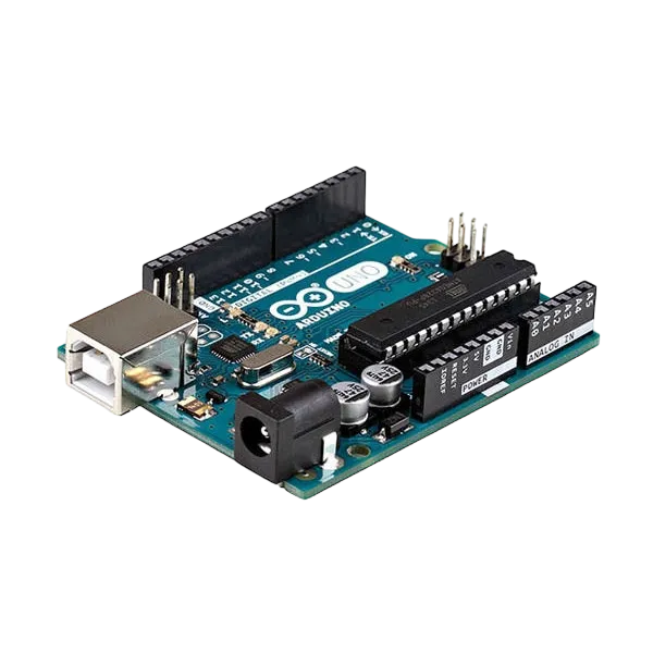 |
 |
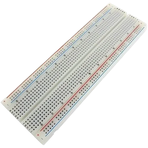 |
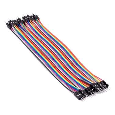 |
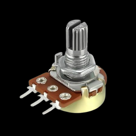 |
 |
|---|---|---|---|---|---|
Building the circuit
Things Needed:
- Arduino Uno = 1
- Arduino USB cable = 1
- Potentiometer = 1
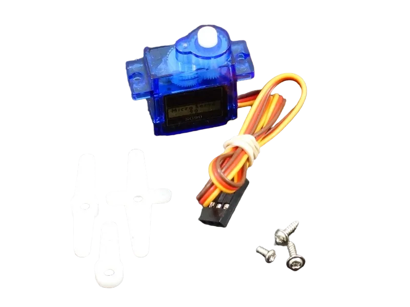
- Servo motor = 1
- Breadboard = 1
- Jumper wires
Mounting the component on the breadboard
Step 1: Place the Potentiometer on the breadboard.

NB: Make sure all components are securely placed on the breadboard with correct orientation.
WIRING THE CIRCUIT
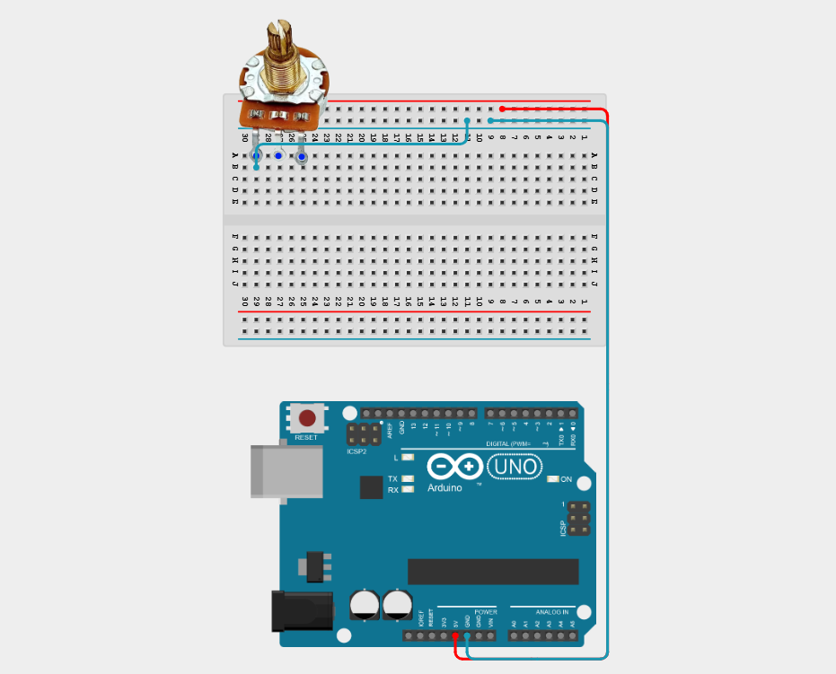
Step 2: Connect the 5V pin on the Arduino to the positive (+) power rail of the breadboard using male-to-male jumper wires.

Step 3: Connect the GND pin on the Arduino to the negative (–) power rail of the breadboard using male-to-male jumper wires.

The power rails will now supply power to multiple components.
Step 4: Connect one outer pin of the Potentiometer to the GND (-) rail on the Breadboard using male-to-male jumper wire.
Step 5: Connect the other outer pin of the Potentiometer to the 5V (+) rail on the Breadboard using male-to-male jumper wire.

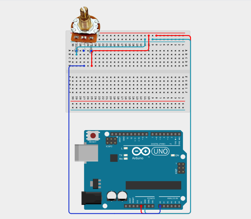
Step 6: Connect the middle pin of the Potentiometer to Analog Pin A0 on the Arduino using male-to-male jumper wire.

Step 7: Connect the Signal (Orange/Yellow) of the Servo Motor to Digital Pin 9 on the Arduino using male-to-male jumper wire.
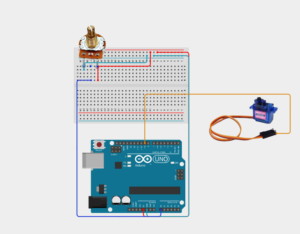
Step 8: Connect the VCC (Red) wire of the Servo Motor to the 5V (+) rail on the breadboard using male-to-male jumper wire.
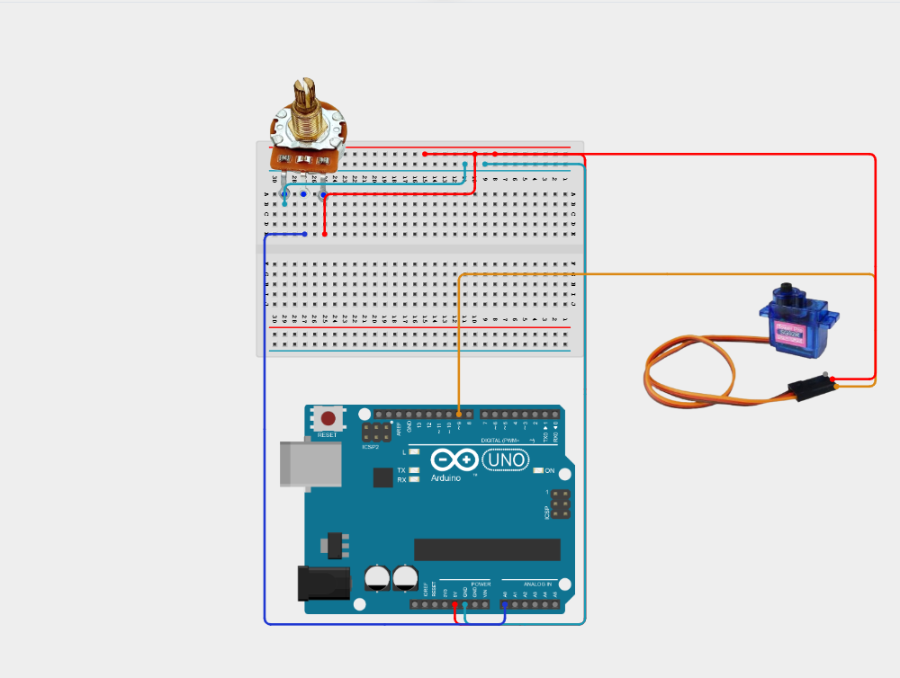
Step 9: Connect the GND (Brown/Black) wire to the GND (-) rail on the breadboard using male-to-male jumper wire.

Make sure to connect the Arduino USB cable to the Arduino board. Place the Servo Blade firmly on the Servo Motor.
PROGRAMMING
Step 1: Open your Arduino IDE. See how to set up here: Getting Started.
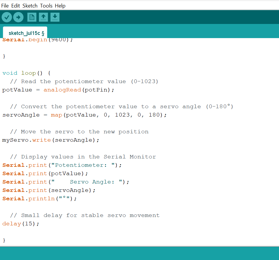
Step 2: Type the following code in your Arduino IDE: #include <Servo.h>,const int potPin = A0;, const int servoPin = 9;, Servo myServo;, int potValue;, int servoAngle; as shown in the image below.

Step 3: Type the following code in your Arduino inside the void setup() myServo.attach(servoPin);,Serial.begin(9600); as shown in the image below.

Step 4: Type the following code in your Arduino IDE: potValue = analogRead(potPin);, servoAngle = map(potValue, 0, 1023, 0, 180);, myServo.write(servoAngle);, Serial.print("Potentiometer: ");, Serial.print(potValue);, Serial.print(" Servo Angle: ");, Serial.print(servoAngle);, Serial.println("°");, delay(15); as shown in the image below.
Uploading the code
Step 1: Save your code. See the Getting Started section
Step 2: Select the Arduino board and port. See the Getting Started section
Step 3: Upload your code.
CONCLUSION
This project helps learners understand how to combine multiple components with Arduino to create more complex interactive systems and automation solutions.