Project 2.9.3: Mechanical Expression Display
| Description | This project makes a servo motor rotate a simulated robot head while the RGB LED changes eye colors for expressive effects. |
|---|---|
| Use case | This project can be used in educational robotics, interactive exhibits, STEM demonstrations, and robotic companions to simulate expressive head movements and changing eye colors for enhanced human-robot interaction. |
Components (Things You will need)
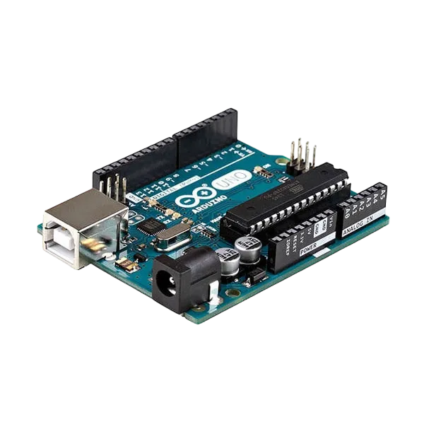 |
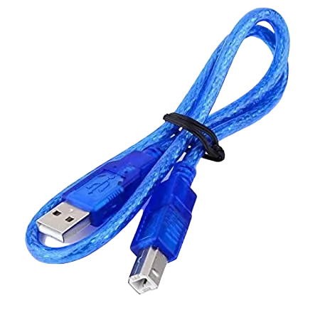 |
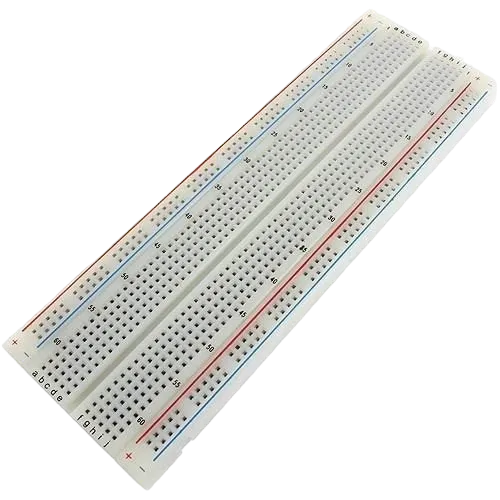 |
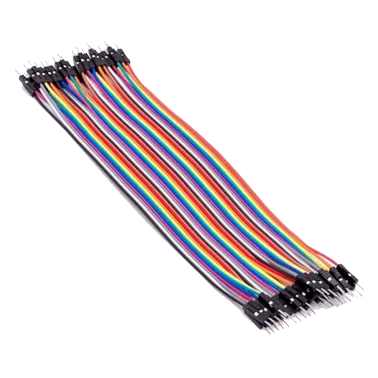 |
 |
 |
|---|---|---|---|---|---|
Building the circuit
Things Needed:
- Arduino Uno = 1
- Arduino USB cable = 1
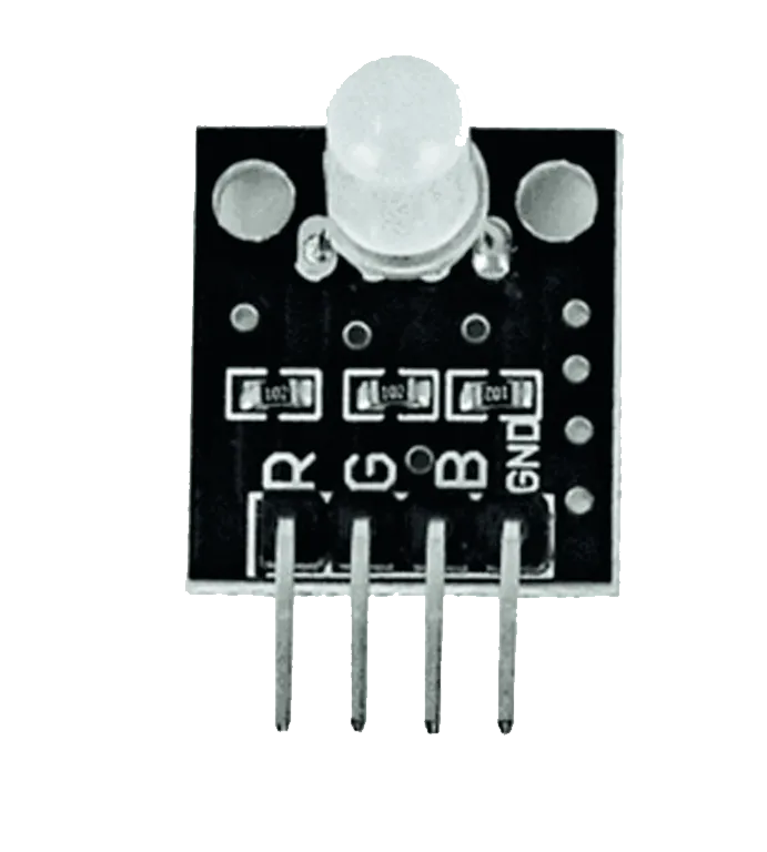
- RGB LED module = 1
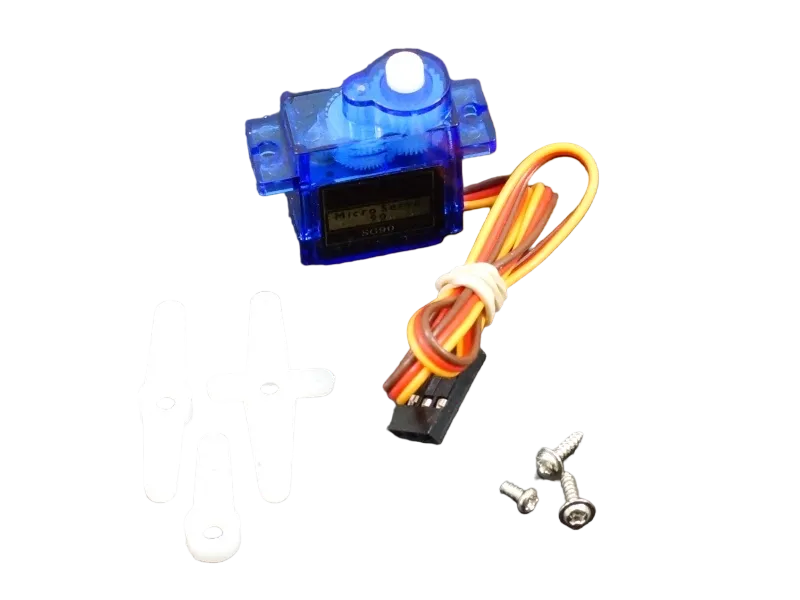
- Servo motor = 1
- Breadboard = 1
- Jumper wires
Mounting the component on the breadboard
Step 1: Place the RGB LED Module on the breadboard.

NB: Make sure all components are securely placed on the breadboard with correct orientation.
WIRING THE CIRCUIT
Step 2: Connect the Signal (Orange/Yellow) of the Servo Motor wire to Digital Pin 9 on the Arduino Uno using male-to-male jumper wire.

Step 3: Connect the VCC (Red) of the Servo Motor wire to 5V on the Arduino Uno using male-to-male jumper wire.
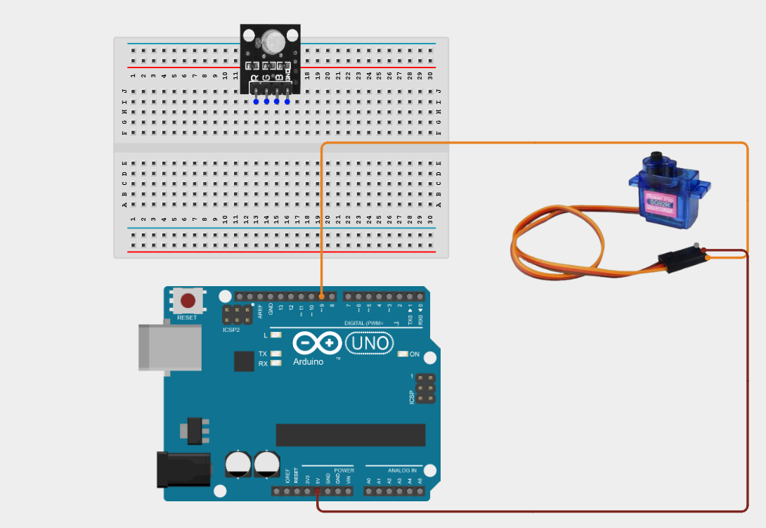
Step 4: Connect the GND (Brown/Black) of the Servo Motor wire to GND on the Arduino Uno using male-to-male jumper wire.

Step 5: Connect the Red (R) pin of the RGB LED to Digital Pin 3 on the Arduino Uno using male-to-male jumper wire.

Step 6: Connect the Green (G) pin of the RGB LED to Digital Pin 5 on the Arduino Uno using male-to-male jumper wire.

Step 7: Connect the Blue (B) pin of the RGB LED to Digital Pin 6 on the Arduino Uno using male-to-male jumper wire.

Step 8: Connect the GND pin of the RGB LED to GND on the Arduino Uno using male-to-male jumper wire.

Make sure to connect the Arduino USB cable to the Arduino board.
PROGRAMMING
Step 1: Open your Arduino IDE. See how to set up here: Getting Started.
Step 2: Type the following code in your Arduino IDE: #include <Servo.h>, const int servoPin = 9;, const int redPin = 3;, const int greenPin = 5;, const int bluePin = 6;,Servo robotHead; as shown in the image below.

Step 3: Type the following code in your Arduino IDE inside the void setup() function: robotHead.attach(servoPin);, pinMode(redPin, OUTPUT);, pinMode(greenPin, OUTPUT);, pinMode(bluePin, OUTPUT);, robotHead.write(90); as shown in the image below.

Step 4: Type the following code in your Arduino IDE inside the void loop() function: setColor(0, 0, 255);, for (int angle = 90; angle >= 0; angle--) {, robotHead.write(angle);, delay(15); }, delay(500);, setColor(0, 255, 0);, for (int angle = 0; angle <= 180; angle++) {;, delay(500);, robotHead.write(angle);, delay(15); }, delay(500); as shown in the image below.

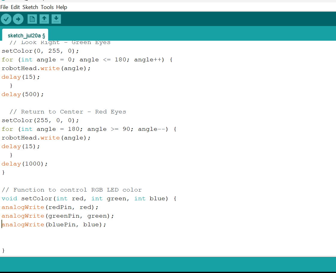
Step 5: Type the following code in your Arduino IDE inside the void loop() function: setColor(255, 0, 0);, for (int angle = 180; angle >= 90; angle--) {, robotHead.write(angle);, delay(15); }, delay(1000);, void setColor(int red, int green, int blue) {, analogWrite(redPin, red);, analogWrite(greenPin, green);, analogWrite(bluePin, blue); } as shown in the image below.
Uploading the code
Step 1: Save your code. See the Getting Started section
Step 2: Select the Arduino board and port. See the Getting Started section
Step 3: Upload your code.
CONCLUSION
This project helps learners understand how to combine multiple components with Arduino to create more complex interactive systems and automation solutions.