Project 1.9.2: Sound Level Trigger
| Description | This project shows how to monitor audio amplitude spikes using the sound sensor module and log threshold crossings to the Serial Monitor. |
|---|---|
| Use case | This project can be used in noise monitoring systems, industrial equipment monitoring, classroom or laboratory demonstrations, and environmental data logging to detect and record sudden increases in sound levels. |
Components (Things You will need)
 |
 |
 |
 |
 |
|---|---|---|---|---|
Building the circuit
Things Needed:
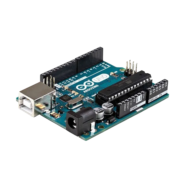
- Arduino Uno = 1
- Arduino USB cable = 1
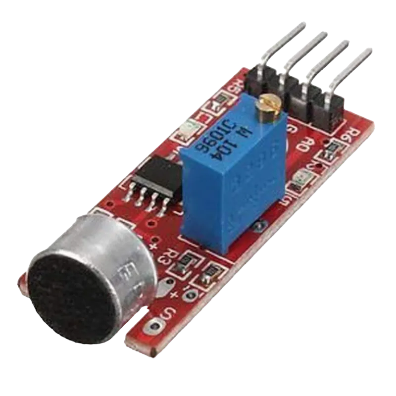
- Sound sensor module = 1
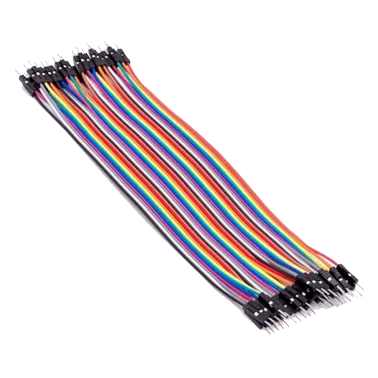
- Jumper wires
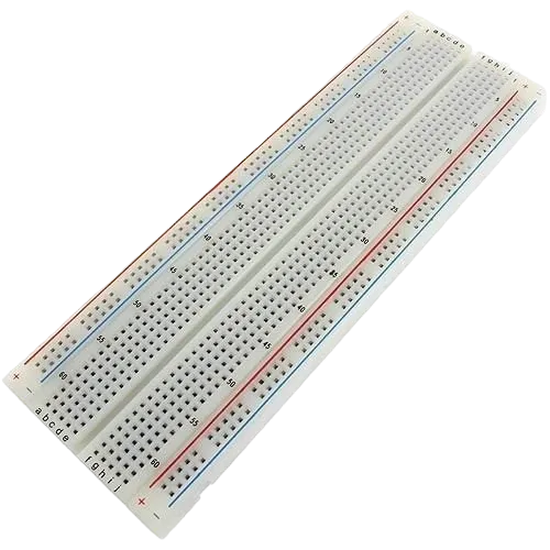
Mounting the component on the breadboard
Step 1: Place the sound sensor module on the breadboard.
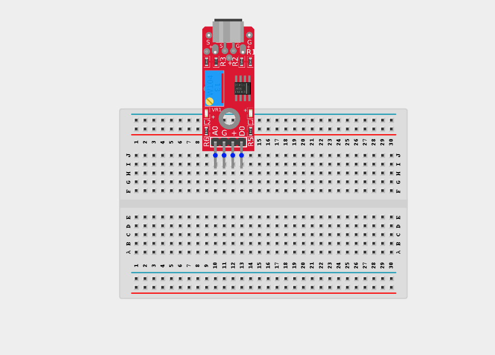
NB: Make sure you identify the correct pin connections for the component.
WIRING THE CIRCUIT
Step 2: Connect the red jumper wire to the positive pin (+)/ VCC of the sound sensor and the other end to 5V on the Arduino Uno.

Step 3: Connect the blue jumper wire to the negative pin (-)/ GND of the sound sensor and the other end to GND on the Arduino Uno.
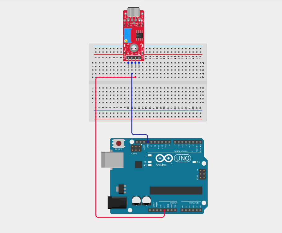
Step 4: Connect the green jumper wire to the D0 of the sound sensor and the other end to digital pin 4 on the Arduino Uno.

Make sure to connect the Arduino USB cable to the Arduino board.
PROGRAMMING
Step 1: Open your Arduino IDE. See how to set up here: Getting Started.
Step 2: Type int soundPin = 4; as shown in the image below.

NB: Declare the sound sensor analog pin
Step 3: Type int threshold = 600; as shown in the image below.

NB: Set noise threshold value
Step 4: Type int soundValue = 0; as shown in the image below.

NB: Variable to store sound reading
Step 5: Type the following code inside the void setup(){} function pinMode(soundPin, INPUT);

NB: Set sound pin as input
Step 6: Type the following code inside the void loop(){} soundValue = analogRead(soundPin);

NB: Read sound sensor value
Step 7: Type Serial.print("Sound: "); Serial.println(soundValue); as shown in the image below.
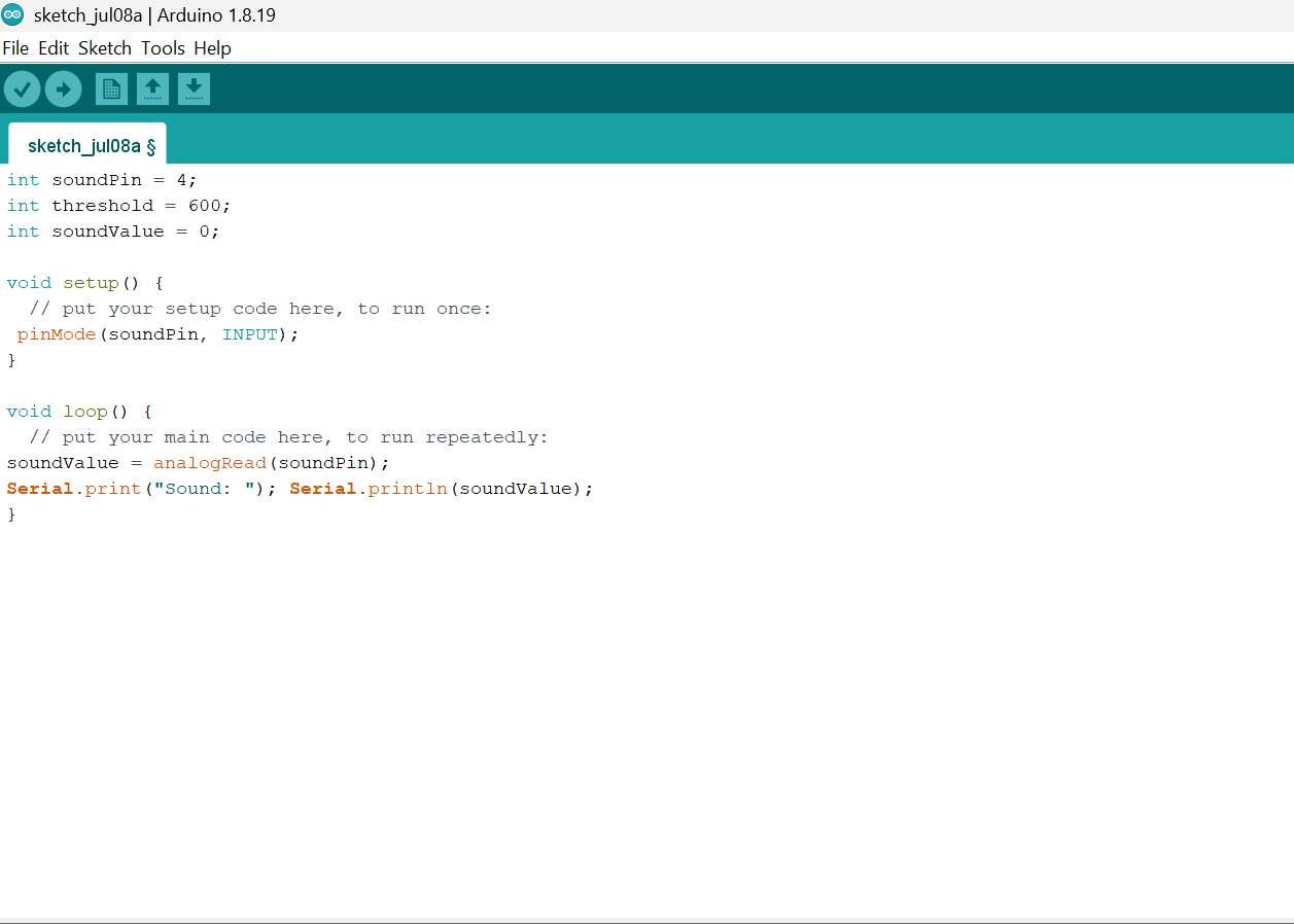
NB: Print sound level
Step 8: Type if (soundValue > threshold) { as shown in the image below.
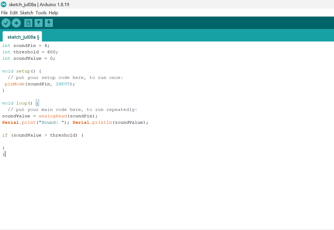
NB: Check if threshold exceeded
Step 9: Type Serial.println("NOISE DETECTED!"); as shown in the image below.

NB: Alert message
Step 10: Type delay(200); } as shown in the image below.
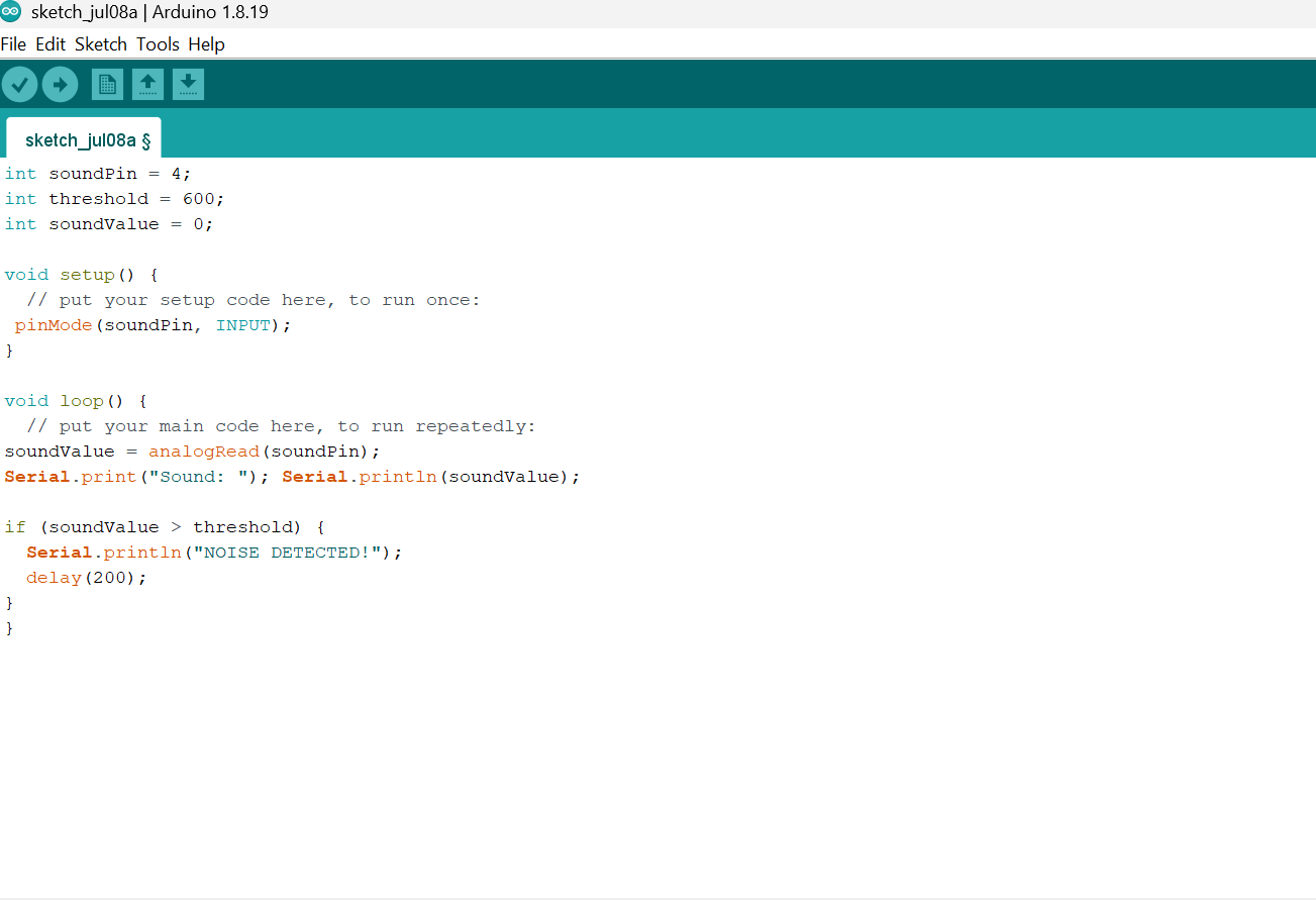
NB: Cooldown to prevent repeated triggers
Step 11: Save your code. See the Getting Started section
Step 12: Select the Arduino board and port. See the Getting Started section
Step 13: Upload your code.
Step 14: Open the Serial Monitor (Tools > Serial Monitor) to view the output.
EXPLANATION
soundPin = 4; reads digital sound values from the sensor. threshold sets the sensitivity level for detection. digitalRead(soundPin) returns a value proportional to sound amplitude. When a loud sound occurs, the value spikes above the threshold.
CONCLUSION
This project helps learners understand how to interface with Sound Sensor using Arduino. It introduces essential concepts in electronic circuits and embedded system programming.