Project 1.4.4: Traffic Light Red Only Blink
| Description | This is where you get to know how to make the red LED blink. |
|---|---|
| Use case | Programming the red light on the traffic to blink which could be used to signal danger on the road. |
Components (Things You will need)
 |
 |
 |
 |
 |
|---|---|---|---|---|
Building the circuit
Things Needed:
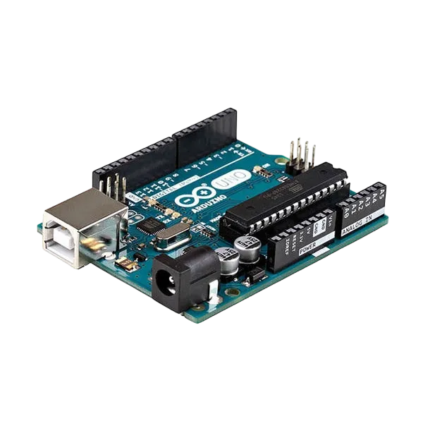
- Arduino Uno = 1
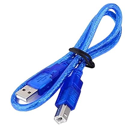
- Arduino USB cable = 1
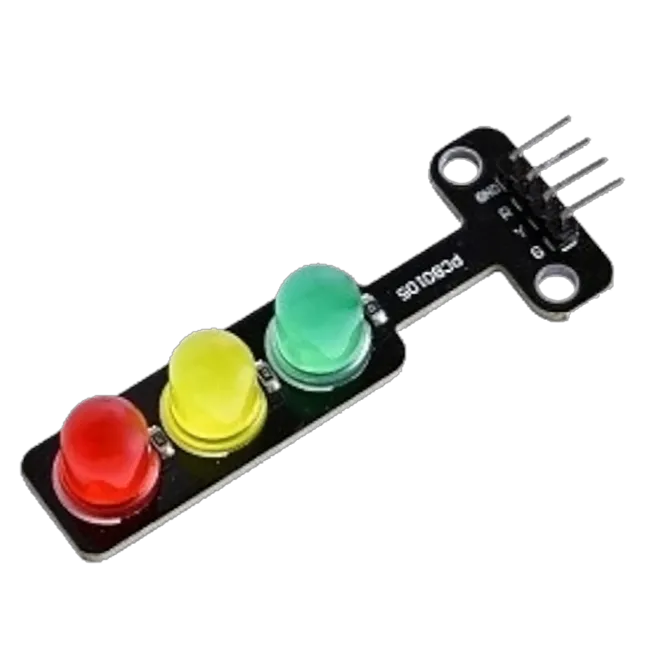
- Traffic light module = 1
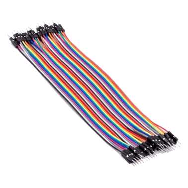
- Jumper Wires
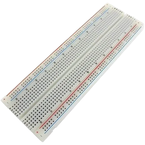
Mounting the component on the breadboard
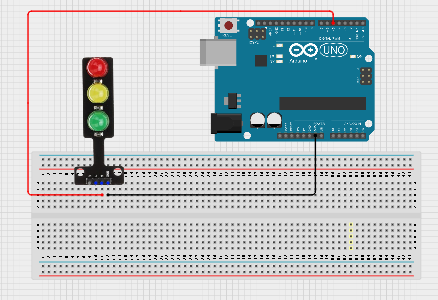
Step 1: Place the traffic light module on the breadboard.
step 2:Connect the G pin of the traffic light module to pin 5 on the Arduino Uno using a jumper wire.
step 3:Connect the GND pin of the traffic light module to GND on the Arduino Uno.
step 4:After wiring, connect the Arduino Uno to the computer using the USB cable.
 .
.
PROGRAMMING
Step 1: Open your Arduino IDE. See how to set up here: Getting Started.
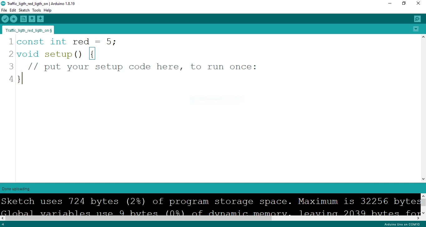
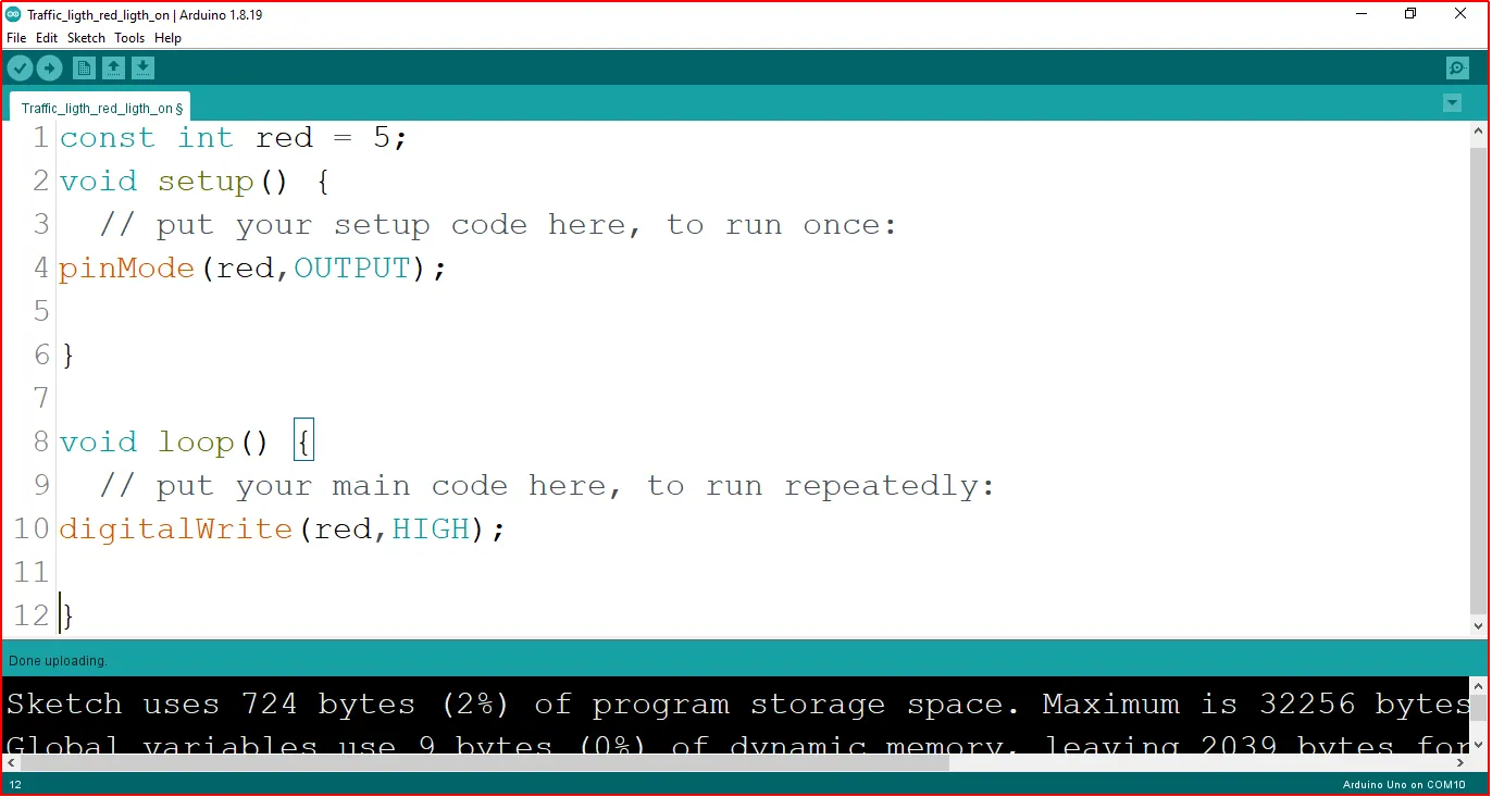
Step 2: Type const int red = 5; before the void setup function.
 .
.
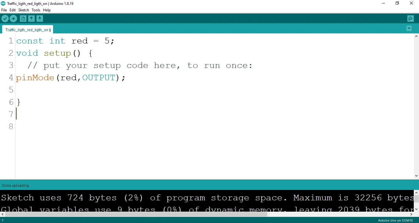
Step 3: Type the following codes in the void setup function as shown below;
pinMode (red, OUTPUT);
 .
.
Step 4: Type the following codes in the void loop function as shown below;
digitalWrite (red, HIGH);
 .
.
The digitalWrite () function controls the state of the pin. The pin can either be HIGH or LOW. The HIGH state turns on the LED. As a result, the code below turns on the LED.
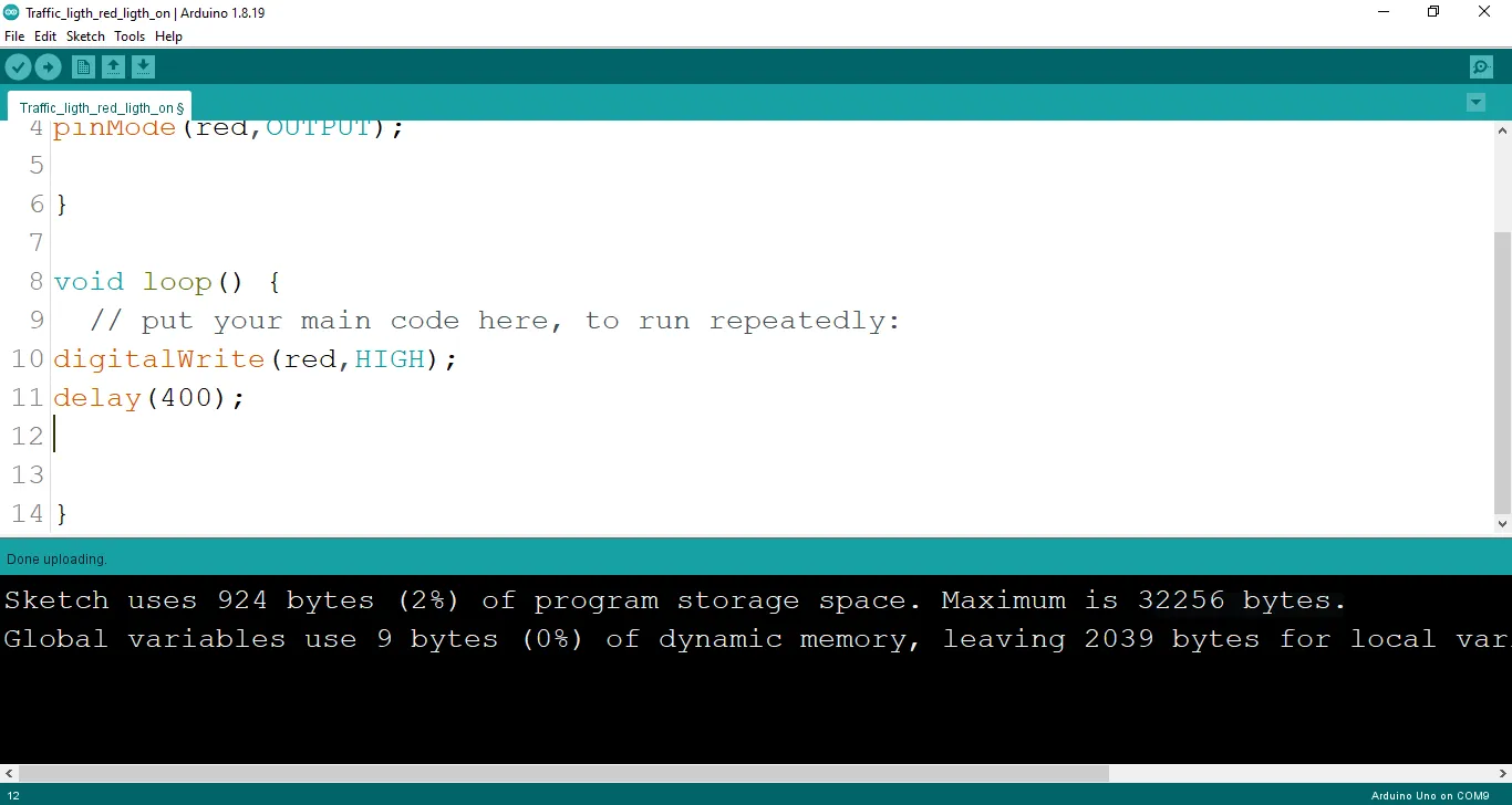
Step 5: Now, let's introduce a delay by typing delay(400); exactly as shown in the image below.
 .
.
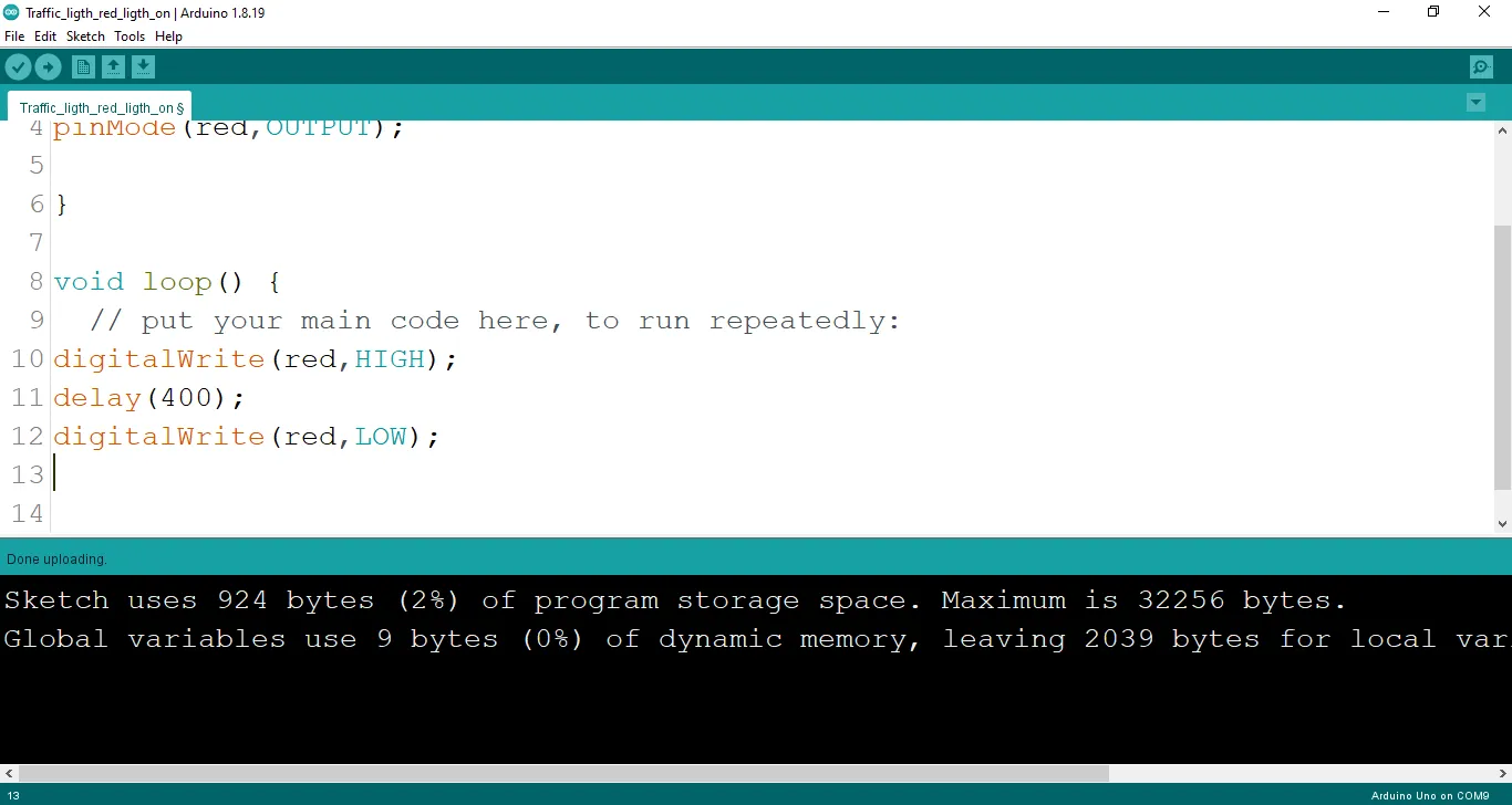
Step 6: : Type digitalWrite (red, LOW); exactly as shown in the image below.
 .
.
Step 7: Now, let's finish up with a delay by typing delay(400); exactly as shown in the image below.
.
Uploading the code
Step 1: Save your code. See the Getting Started section
Step 2: Select the arduino board and port See the Getting Started section:Selecting Arduino Board Type and Uploading your code.
Step 3: Upload your code. See the Getting Started section:Selecting Arduino Board Type and Uploading your code
OBSERVATION
When the circuit is functioning, observe the Red LED of the traffic light blinking as expected. This indicates that the LED is receiving the signal correctly from the Arduino and is operating as intended.
CONCLUSION
The project focusing on creating a blinking red light within a simulated traffic light system offers an engaging introduction to controlled visual signaling. By programming the red LED to blink, participants learn about timing control, code logic, and the significance of rhythmic signaling. This endeavor serves as a foundational step in electronics exploration, showcasing the concept of dynamic visual cues and sparking curiosity about practical applications, such as traffic safety and automation.